Download Careers360 App
Force Between Two Parallel Current Carrying Conductors

Force Between Two Parallel Current Carrying Conductors

Edited By Vishal kumar | Updated on Jul 02, 2025 05:55 PM IST

The force between two parallel current-carrying conductors is a fundamental concept in electromagnetism that finds applications in both theoretical physics and practical engineering. When two wires carrying electric currents are placed close to each other, they exert a force on one another due to the interaction of their magnetic fields. If the currents flow in the same direction, the wires attract; if the currents flow in opposite directions, the wires repel. This principle is not just an academic exercise; it has real-life applications in the design of electrical devices such as transformers, electric motors, and power transmission lines. Understanding this force helps engineers optimize the efficiency and stability of these systems, ensuring that the infrastructure supporting modern technology remains robust and reliable. For instance, in power lines, managing the force between conductors can reduce energy losses and prevent potential hazards. In this article, we will study the force between parallel conductors. It is essential for both advancing scientific knowledge and improving everyday electrical technology

This Story also Contains
  1. Force Between Two Parallel Current-Carrying Infinite Wires
  2. Solved Examples Based on Force between Two Parallel Current Carrying Infinite Wires
  3. Summary
Force Between Two Parallel Current Carrying Conductors

Force Between Two Parallel Current-Carrying Infinite Wires

The force between two parallel current-carrying infinite wires is a classic problem in electromagnetism that illustrates the interaction of magnetic fields generated by electric currents. When two infinitely long, straight conductors are placed parallel to each other and carry currents, they experience a magnetic force due to the magnetic fields each wire generates. If the currents in both wires flow in the same direction, the wires attract each other. Conversely, if the currents flow in opposite directions, the wires repel each other.

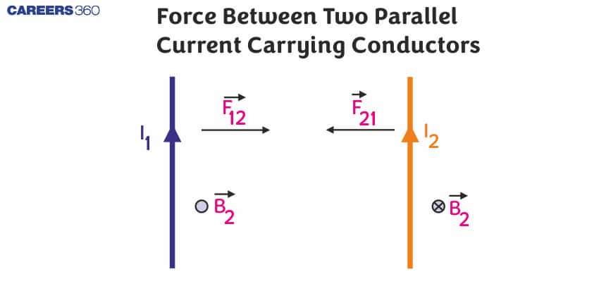
Let us take two long straight conductors carrying currents $i_1$ and place them parallel to each other at a distance ‘a’ from each other as shown in the figure

Now, from the earlier concept which we have studied before, we can say that conductor 2 experiences the same magnetic field at every point along its length due to conductor 1. Because of this there will be some force acting on conductor 2 and the direction of magnetic force is indicated in the figure and it can be visualised by using the right-hand thumb rule.

Now, if we apply Ampere's circuital law on the first conductor then the magnitude of the magnetic field can be obtained as

$B_1=\frac{\mu_0 I_1}{2 \pi a}$

Then the force on a segment of length L of conductor 2 due to conductor 1 can be given as,

$F_{21}=I_2 L B_1=\frac{\mu_0 I_1 I_2}{2 \pi a} L$

Similarly, we can calculate the force exerted by the conductor 2 on the conductor 1. We see that the conductor 1 experiences the same force due to the conductor 2 but the direction of force is opposite. Thus we can say that,

$F_{21}=F_{12}$ (But the direction will be opposite.)

But if the direction of current flowing through the conductor is opposite in both the conductors then both the wires will repel each other.

Also, the magnitude of the force acting per unit length can be given as

$f_{12}=f_{21}=\frac{\mu_0 I_1 I_2}{2 \pi a}$

Recommended Topic Video

Solved Examples Based on Force between Two Parallel Current Carrying Infinite Wires

Example 1: Two wires A & B are carrying currents $I_1 \& I_2$ as shown in the figure. The separation between them is d. A third wire C carrying a current I is to be kept parallel to them at a distance x from A such that the net force acting on it is zero. The possible values of x are:

1) $x=\left(\frac{I_1}{I_1-I_2}\right) d \quad$ and $\quad x=\left(\frac{I_2}{I_1+I_2}\right) d$
2) $x=\left(\frac{I_2}{I_1+I_2}\right) d$ and $x=\left(\frac{I_2}{I_1-I_2}\right) d$
3) $x=\left(\frac{I_1}{I_1+I_2}\right) d$ and $x=\left(\frac{I_2}{I_1-I_2}\right) d$
4) $x= \pm\left(\frac{I_1}{I_1-I_2}\right) d$

Solution:

when $I_2>I_1$ ( that is wire 3 is on the left side of both 1&2)

For equilibrium,

$\begin{aligned} & F_{31}=F_{32} \\ & \frac{\mu_o I_1 I l}{2 \pi x}=\frac{\mu_o I_2 I l}{2 \pi(d+x)} \\ & \frac{d+x}{x}=\frac{I_2}{I_1} \\ & \quad x=\left(\frac{I_1}{I_2-I_1}\right) d\end{aligned}$........(I)

when $I_1>I_2$ ( that is wire 3 is on the right side of both 1&2)

$\begin{aligned} & F_{31}=F_{32} \\ & \frac{\mu_o I_1 I l}{2 \pi x}=\frac{\mu_o I_2 I l}{2 \pi(x-d)} \\ & \frac{x-d}{x}=\frac{I_2}{I_1} \\ & x=\left(\frac{-I_1}{I_2-I_1}\right) d\end{aligned}$......(II)

from (1) & (2)

$x= \pm\left(\frac{I_1 d}{I_1-I_2}\right)$

Hence the answer is the option (4).

Example 2: A rigid square loop of side a and carrying current $I_2$ is lying on a horizontal surface near a long current $I_1$ carrying wire in the same plane as shown in the figure. The net force on the loop due to the wire will be :

1) Repulsive and equal to $\frac{\mu_0 I_1 I_2}{2 \pi}$
2) Attractive and equal to $\frac{\mu_0 I_1 I_2}{3 \pi}$
3) Repulsive and equal to $\frac{\mu_0 I_1 I_2}{4 \pi}$
4) Zero

Solution:

$\begin{aligned} & F_1=\frac{\mu_0 I_1 I_2 a}{2 \pi a}=\frac{\mu_0 I_1 I_2}{2 \pi} \\ & F_2=\frac{\mu_0 I_1 I_2 a}{2 \pi .2 a}=\frac{\mu_0 I_1 I_2}{4 \pi} \\ & F_{\text {Total }}=F_1-F_2 \\ & =\frac{\mu_0 I_1 I_2}{2 \pi}-\frac{\mu_0 I_1 I_2}{4 \pi} \\ & =\frac{\mu_0 I_1 I_2}{4 \pi} \\ & \text { to right Repulsive } \\ & \end{aligned}$

Hence the answer is the option (1).

Example 3: Two concentric coils each of radius equal to $2 \pi$ cm are placed at right angles to each other. 3 ampere and 4 ampere are the currents flowing in each coil respectively. The magnetic induction in Weber/m2 at the centre of the coils will be $\left(\mu_0=4 \pi \times 10^{-7} \mathrm{~Wb} / \mathrm{A}-\mathrm{m}\right)$

1) $5 \times 10^{-5}$
2) $7 \times 10^{-5}$
3) $12 \times 10^{-5}$
4) $10^{-5}$

Solution:

Concentric loops but their planes are perpendicular to each other

$\begin{aligned} & B=\sqrt{B_1^2+B_2^2} \\ & B=\frac{\mu_o}{2 r} \sqrt{i_1^2+i_2^2}\end{aligned}$

wherein

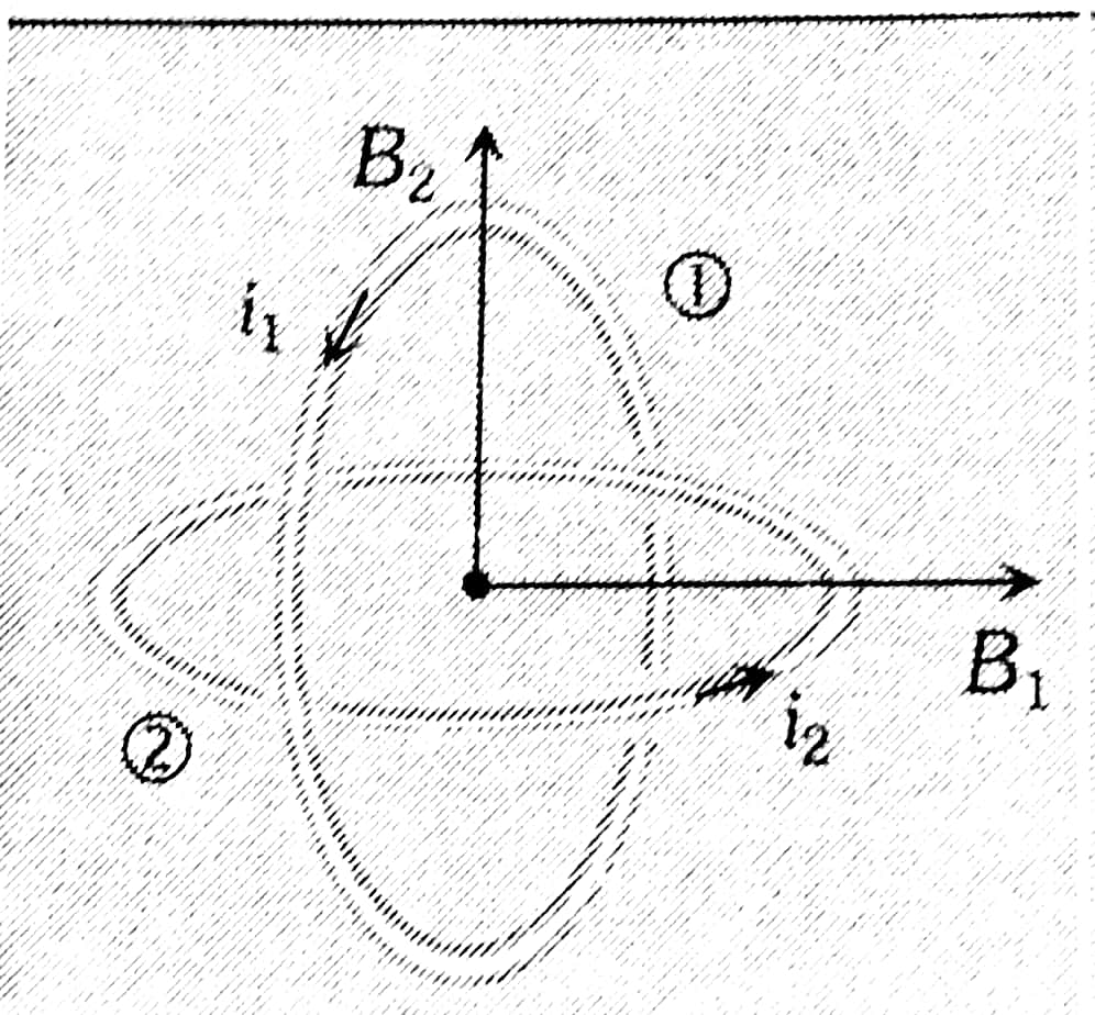
Magnetic induction at the centre of one coil $B_1=\frac{\mu_0 i_1}{2 r}$

Similarly $\quad B_2=\frac{\mu_0 i_2}{2 r}$
$
\begin{aligned}
& \therefore \quad B^2=B_1^2+B_2^2=\left(\frac{\mu_0 i_1}{2 r}\right)^2+\left(\frac{\mu_0 i_2}{2 r}\right)^2 \\
& =\frac{\mu_0^2}{4 r^2}\left(i_1^2+i_2^2\right) \\
& \therefore \quad B=\frac{\mu_0}{2 r} \sqrt{i_1^2+i_2^2} \\
& =\frac{4 \pi \times 10^{-7}}{2 \times\left(2 \pi \times 10^{-2}\right)} \sqrt{(3)^2+(4)^2} \\
& \text { or } B=5 \times 10^{-5} \mathrm{~Wb} / \mathrm{m}^2
\end{aligned}
$

Hence the answer is the option (1).

Example 4: Two similar coils are kept mutually perpendicular such that their centres coincide at the centre. Find the ratio of the magnetic field of one coil to the resultant magnetic field by both coils if the same current is flown.

1) $1: \sqrt{2}$
2) $1: 2$
3) $2: 1$
4) $\sqrt{3}: 1$

Solution:

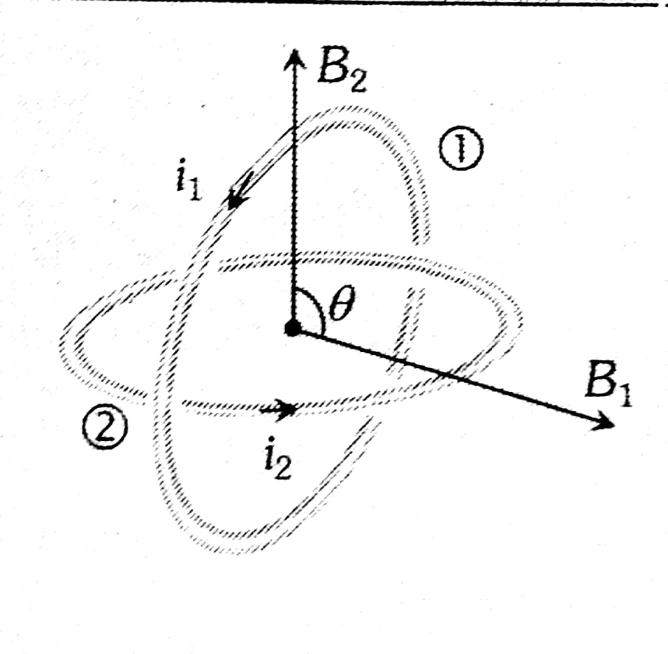
Concentric loops but their planes are at an angle $\theta$ with each other

$B=\sqrt{B_1^2+B_2^2+2 B_1 B_2 \cos \theta}$

wherein

But,

$\begin{aligned} B_{\text {net }} & =\sqrt{2} B \\ \frac{B}{B_{\text {net }}} & =\frac{1}{\sqrt{2}}\end{aligned}$

Hence the answer is the option (1).

Example 5: Two long parallel conductors $S_1$ and $S_2$ are separated by a distance of 10 cm and carrying currents of 4 A and 2A respectively. The conductors are placed along the x-axis in the X-Y plane. There is a point P located between the conductors (as shown in the figure). A charged particle of $3 \pi$ coulomb is passing through the point P with velocity $\vec{v}=(2 \hat{\mathrm{i}}+3 \hat{\mathrm{j}}) \mathrm{m} / \mathrm{s}$; where $\hat{\mathrm{i}}_{\mathrm{i}} \& \hat{\mathrm{j}}$ represents unit vector along $x \& y$ axis respectively. The force acting on the charged particle is $4 \pi \times 10^{-u}(-x i+2 \mathrm{j}) \mathrm{N}$. The value of x is :

1) 2

2) 1

3) 3

4) -3

Solution:


Charge particle will experience a force due to the magnetic field produced by current-carrying wired using Lorentz force equation
$\vec{F}=q(\vec{v} \times \vec{B})$
To calculate the magnetic field at 'P'

$\begin{aligned} \vec{B} & =\mathrm{B}_1(-\hat{\mathrm{k}})+\mathrm{B}_2 \hat{\mathrm{k}} \\ & =\frac{\mu_0 \times 4}{2 \pi \times 4 \times 10^{-2}}(-\hat{\mathrm{k}})+\frac{\mu_0 \times 2}{2 \pi \times 6 \times 10^{-2}}(\hat{\mathrm{k}}) \\ & =\frac{\mu_0}{\pi} \times 10^2\left[\frac{-1}{2}+\frac{1}{6}\right] \hat{\mathrm{k}} \\ \vec{B} & =\frac{\mu_0}{3 \pi} \times 10^2(-\hat{\mathrm{k}}) \\ \vec{F} & =3 \pi\left[(2 \hat{\mathrm{i}}+3 \hat{\mathrm{j}}) \times\left(\frac{\mu_0}{3 \pi} \times 10^{+2}\right)(-\hat{\mathrm{k}})\right] \\ & =10^{+2} \times \mu_0[2 \hat{\mathrm{j}}-3 \hat{\mathrm{i}}] \\ & =4 \pi \times 10^{-7} \times 10^2[2 \hat{\mathrm{j}}-3 \hat{\mathrm{i}}] \\ & =4 \pi \times 10^{-5} \times[-3 \hat{\mathrm{i}}+2 \hat{\mathrm{j}}] \\ \mathrm{x} & =3\end{aligned}$

Hence the answer is the option (3).

Summary

The force between two parallel current-carrying infinite wires is a fundamental aspect of electromagnetism, driven by the interaction of their magnetic fields. If currents flow in the same direction, the wires attract; if opposite, they repel. The force per unit length between the wires can be expressed using Ampère's law. This concept is crucial for understanding practical applications such as power transmission and electric motors. Solved examples illustrate the calculation of forces and equilibrium conditions in various configurations, emphasizing the importance of this principle in both theoretical and applied physics.

Frequently Asked Questions (FAQs)

1. What causes the force between two parallel current-carrying conductors?
The force between two parallel current-carrying conductors is caused by the magnetic fields generated by each conductor. When current flows through a wire, it creates a circular magnetic field around it. These magnetic fields interact with each other, resulting in an attractive force if the currents are in the same direction, or a repulsive force if the currents are in opposite directions.
2. How does the direction of current affect the force between parallel conductors?
The direction of current determines whether the force between parallel conductors is attractive or repulsive. If the currents in both conductors flow in the same direction, the force is attractive, pulling the conductors towards each other. If the currents flow in opposite directions, the force is repulsive, pushing the conductors apart.
3. What is the relationship between the force and the distance between the conductors?
The force between two parallel current-carrying conductors is inversely proportional to the distance between them. This means that as the distance between the conductors increases, the force decreases, and vice versa. Mathematically, this is expressed as F ∝ 1/r, where F is the force and r is the distance between the conductors.
4. How does the magnitude of current affect the force between parallel conductors?
The force between parallel current-carrying conductors is directly proportional to the product of the currents in both conductors. This means that if you increase the current in either or both conductors, the force between them will increase. Mathematically, this is expressed as F ∝ I1 × I2, where F is the force and I1 and I2 are the currents in the two conductors.
5. What is the formula for calculating the force per unit length between two parallel current-carrying conductors?
The formula for calculating the force per unit length (F/L) between two parallel current-carrying conductors is:
6. Can the force between parallel conductors be zero? If so, under what conditions?
Yes, the force between parallel conductors can be zero under two conditions:
7. How does the length of the conductors affect the total force between them?
The length of the conductors is directly proportional to the total force between them. The formula we typically use (F/L) gives the force per unit length. To find the total force, you multiply this by the length of the conductors (assuming they are of equal length). So, doubling the length of the conductors would double the total force between them.
8. What would happen to the force if you doubled the current in both conductors?
If you doubled the current in both conductors, the force between them would increase by a factor of four. This is because the force is proportional to the product of the currents in the two conductors (F ∝ I1 × I2). So if I1 becomes 2I1 and I2 becomes 2I2, the new force would be proportional to (2I1) × (2I2) = 4(I1 × I2), which is four times the original force.
9. What is the significance of the force between parallel conductors in the design of electrical equipment?
The force between parallel conductors is significant in the design of electrical equipment for several reasons:
10. How does the force between parallel conductors change if you replace one conductor with a permanent magnet?
If you replace one conductor with a permanent magnet, the basic principle remains similar, but the calculation becomes more complex. The permanent magnet produces a constant magnetic field, while the current-carrying conductor produces a field proportional to its current. The force would still depend on the strength of the magnetic field, the current in the remaining conductor, and the distance between them. However, the force would no longer depend on the current in both conductors, and its direction would depend on the orientation of the magnet's poles.
11. How does the shape of the conductors affect the force between them?
The shape of the conductors can affect the force between them, but the effect is usually negligible for thin, straight conductors. The formula for the force between parallel conductors assumes infinitely long, straight conductors with negligible cross-sectional area. In reality, slight variations in shape or thickness can cause small deviations from the ideal case. For significantly different shapes (like loops or coils), different formulas would be needed to accurately calculate the force.
12. What is the significance of the force between parallel conductors in the context of plasma physics?
In plasma physics, the force between parallel currents is crucial in understanding plasma behavior and confinement. Plasmas often contain current channels, which can attract or repel each other much like solid conductors. This force plays a role in:
13. Why is the force between parallel current-carrying conductors used to define the ampere?
The force between parallel current-carrying conductors is used to define the ampere because it provides a precise and reproducible way to measure electric current. The ampere is defined as the constant current that, if maintained in two straight parallel conductors of infinite length, of negligible circular cross-section, and placed 1 meter apart in vacuum, would produce between these conductors a force equal to 2 × 10^-7 newton per meter of length.
14. How does the permeability of the medium affect the force between parallel conductors?
The permeability of the medium directly affects the force between parallel conductors. The force is directly proportional to the permeability of the medium in which the conductors are placed. In most calculations, we use μ0, the permeability of free space. However, if the conductors are in a different medium, the permeability of that medium would be used, which could increase or decrease the force compared to the force in vacuum.
15. What happens to the force if you reverse the direction of current in one of the conductors?
If you reverse the direction of current in one of the conductors, the force between the conductors will change from attractive to repulsive (or vice versa). This is because the interaction between the magnetic fields depends on the relative directions of the currents. When the currents are in the same direction, the force is attractive; when they are in opposite directions, the force is repulsive.
16. How does the force between parallel conductors relate to Fleming's Left Hand Rule?
Fleming's Left Hand Rule helps determine the direction of the force on a current-carrying conductor in a magnetic field. In the case of parallel conductors, each conductor creates a magnetic field that affects the other. The force on each conductor can be determined using Fleming's Left Hand Rule: the thumb represents the direction of the current, the forefinger represents the direction of the magnetic field (from the other conductor), and the middle finger gives the direction of the force.
17. Why do parallel conductors carrying current in the same direction attract each other?
Parallel conductors carrying current in the same direction attract each other because of the interaction of their magnetic fields. Each conductor creates a circular magnetic field around itself. When the currents are in the same direction, the magnetic field lines between the conductors are in opposite directions. This creates a region of lower magnetic field strength between the conductors, resulting in a net force that pulls the conductors towards each other.
18. How does the force between parallel conductors relate to the concept of magnetic flux?
The force between parallel conductors is related to magnetic flux through the concept of magnetic field strength. The magnetic flux is a measure of the total magnetic field passing through a given area. In the case of parallel conductors, each conductor creates a magnetic field that penetrates the space around the other conductor. The strength of this field (and thus the flux through any given area) decreases with distance. The force between the conductors is a result of the interaction between the current in one conductor and the magnetic field (flux) from the other.
19. Can the force between parallel conductors be used to measure current?
Yes, the force between parallel conductors can be used to measure current. In fact, this principle is the basis for the definition of the ampere, the SI unit of electric current. By measuring the force between two parallel conductors of known length, separation, and in a known medium, it's possible to determine the current flowing through them. This method is not commonly used in everyday current measurement due to its complexity, but it forms the fundamental basis for current standardization.
20. What is the significance of the μ0/2π term in the force formula?
The term μ0/2π in the force formula (F/L = (μ0 × I1 × I2) / (2π × r)) represents the magnetic field strength at a distance r from a long, straight conductor carrying a current of 1 ampere. This term comes from the application of Ampère's law to a long, straight conductor. It's a constant that relates the strength of the magnetic field to the current producing it and the distance from the conductor.
21. How does the force between parallel conductors relate to Ampère's law?
Ampère's law is fundamental to understanding the force between parallel conductors. It describes how an electric current produces a magnetic field around a conductor. For a long, straight conductor, Ampère's law gives us the magnetic field strength at any distance from the conductor. When we have two parallel conductors, each conductor experiences a force due to the magnetic field produced by the other conductor. The magnitude of this force is calculated using the magnetic field strength (derived from Ampère's law) and the current in the conductor experiencing the force.
22. Can the force between parallel conductors be repulsive? If so, when?
Yes, the force between parallel conductors can be repulsive. This occurs when the currents in the two conductors are flowing in opposite directions. In this case, the magnetic fields interact in such a way that the conductors are pushed apart. The magnitude of the repulsive force is calculated using the same formula as for the attractive force; only the direction changes.
23. How does the force between parallel conductors relate to the right-hand grip rule?
The right-hand grip rule (or right-hand screw rule) is used to determine the direction of the magnetic field around a current-carrying conductor. When applying this rule to parallel conductors, it helps visualize why conductors with currents in the same direction attract and those with opposite currents repel. For example, if you use the right-hand grip rule on two conductors with currents in the same direction, you'll see that the magnetic field between them is in opposite directions, leading to attraction.
24. How does temperature affect the force between parallel current-carrying conductors?
Temperature indirectly affects the force between parallel current-carrying conductors through its impact on the conductors' resistance. As temperature increases, the resistance of most conductors increases. This increased resistance can lead to a decrease in current (if voltage is constant), which would reduce the force between the conductors. Additionally, temperature changes can cause thermal expansion or contraction of the conductors, potentially altering their separation distance, which would also affect the force between them.
25. What is the relationship between the force on parallel conductors and electromagnetic induction?
The force between parallel conductors and electromagnetic induction are both manifestations of electromagnetic interaction, but they represent different aspects of it. The force is a result of the interaction between a current and an external magnetic field. Electromagnetic induction, on the other hand, is the production of a voltage across a conductor when it's exposed to a changing magnetic field. While the force between parallel conductors doesn't directly cause induction, the movement of conductors due to this force can lead to changes in magnetic flux, which can induce voltages in nearby conductors.
26. How does the concept of magnetic dipoles relate to the force between parallel conductors?
While parallel conductors are not typically thought of as magnetic dipoles, the concept can be useful in understanding their interaction. Each current-carrying conductor creates a magnetic field that, at a distance, resembles that of a long magnetic dipole. The interaction between these "dipoles" leads to the attractive or repulsive force between the conductors. This analogy becomes more accurate as the distance between the conductors increases relative to their diameter, and it can be particularly useful in understanding the behavior of current loops or coils.
27. What would happen to the force if the conductors were not perfectly parallel?
If the conductors were not perfectly parallel, the force between them would change. The magnitude of the force would generally decrease as the conductors deviate from being parallel. This is because the force depends on the component of the magnetic field that is perpendicular to the current. As the conductors become less parallel, this perpendicular component decreases. Additionally, a torque might be introduced, tending to align the conductors parallel to each other. The exact behavior would depend on the specific geometry of the conductors.
28. How does the force between parallel conductors relate to the concept of magnetic pressure?
The force between parallel conductors can be understood in terms of magnetic pressure. The magnetic field between the conductors can be thought of as exerting a pressure. When the currents are in the same direction, there's a lower magnetic field strength (and thus lower pressure) between the conductors compared to the outside, resulting in a net inward force. This is analogous to how air pressure differences can cause forces. The concept of magnetic pressure is particularly useful in understanding the behavior of plasmas and in some aspects of astrophysics.
29. Can the force between parallel conductors be used to levitate objects?
Yes, the force between parallel conductors can be used to levitate objects, although it's not the most common method of magnetic levitation. By arranging conductors in specific configurations and controlling the currents, it's possible to create a stable levitation system. This principle is used in some designs of maglev trains, where the repulsive force between current-carrying conductors in the track and the train is used to lift the train off the track. However, most maglev systems use other methods of magnetic levitation for practical reasons.
30. How does the force between parallel conductors relate to the concept of mutual inductance?
The force between parallel conductors and mutual inductance are related concepts, both arising from the magnetic fields created by current-carrying conductors. Mutual inductance refers to the phenomenon where a changing current in one conductor induces a voltage in another nearby conductor. The strength of this mutual inductance depends on the geometry of the conductors and the medium between them, similar to how these factors affect the force between conductors. In fact, the mutual inductance between two conductors can be used to calculate the force between them, as both are fundamentally related to the magnetic flux linking the conductors.
31. How does the force between parallel conductors relate to the Biot-Savart law?
The Biot-Savart law is fundamental to understanding the force between parallel conductors. This law describes how an electric current produces a magnetic field. For parallel conductors, we use the Biot-Savart law to calculate the magnetic field produced by one conductor at the position of the other. Once we know this magnetic field, we can determine the force on the second conductor using the formula F = ILB, where I is the current in the second conductor, L is its length, and B is the magnetic field from the first conductor. The combination of the Biot-Savart law and this force equation leads to the formula for the force between parallel conductors.
32. What would happen to the force if the conductors were placed in a ferromagnetic medium instead of vacuum?
If the parallel conductors were placed in a ferromagnetic medium instead of vacuum, the force between them would significantly increase. Ferromagnetic materials have a much higher magnetic permeability than vacuum. Since the force is directly proportional to the permeability of the medium (represented by μ in the force formula), replacing μ0 (permeability of free space) with the higher permeability of the ferromagnetic medium would result in a stronger force. This is why iron cores are often used in electromagnets and transformers to enhance magnetic effects.
33. How does the force between parallel conductors relate to the concept of magnetic vector potential?
The magnetic vector potential (A) is a fundamental concept in electromagnetism that can be used to derive both the magnetic field and the force between conductors. For parallel conduct

Articles

Back to top