Download Careers360 App
Circuit Diagram - Definition, Diagram, Types, FAQs

Circuit Diagram - Definition, Diagram, Types, FAQs

Edited By Vishal kumar | Updated on Jul 02, 2025 04:25 PM IST

Definition of Circuit Diagram

A circuit is a path that an electric current follows, and a circuit diagram is a visual representation of an electrical circuit.
Students in EEE (Electrical & Electronics Engineering) use numerous drawings or diagrams to demonstrate a specific electrical ckt. These electrical circuits are depicted using lines to represent wires and symbols to indicate electrical and electronic constituents in order to better understand the connections between them. An electric circuit diagram is used by electricians to start any building wiring.
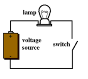
simple circuit diagram
We will learn how to draw a simple electric circuit diagram in this tutorial.

This Story also Contains
  1. Definition of Circuit Diagram
  2. Circuit Diagram-
  3. Types of Circuit Diagram-
  4. How to Build a Simple Electric Circuit?
Circuit Diagram - Definition, Diagram, Types, FAQs
circuit diagram

Circuit Diagram-

The following three components are required to operate an electrical circuit in a simple circuit diagram:

  1. A source of voltage

  2. A conductive channel (a path that allows charges to flow freely) and

  3. A resistor (which can be a light bulb or a motor that works with electricity)

Also read -

Types of Circuit Diagram-

  1. Block Diagram

NEET Highest Scoring Chapters & Topics
This ebook serves as a valuable study guide for NEET exams, specifically designed to assist students in light of recent changes and the removal of certain topics from the NEET exam.
Download E-book

A block diagram is one of the simplest ways to show a complex circuit in its most basic form. It depicts the functioning of the principal components of an electric circuit in the form of blocks, with lines connecting them to indicate the interaction between these blocks, without taking into account the intricate interconnections or wiring.

The following is an example of a block diagram that depicts the process of turning an audio signal into a desired frequency-modulated signal:
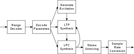
block circuit diagram

  1. Schematic Diagram

The schematic diagram of an electric ckt uses systemized symbols and lines to show all of the ckt's electrical components and linkages.

These diagrams are used to depict series and parallel combinations, as well as the precise connections between their terminals. For example, in a voltage load across resistance and current load across resistance schematic diagram, we use symbols to represent the electrical components and lines to represent the interconnection between their terminals. The schematic diagram circuit is shown in the image below:
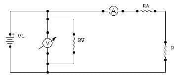
schematic circuit diagram

  1. Pictorial Diagram

One of the most basic diagrams, the pictorial ckt diagram, uses simple pictures of electrical components. These diagrams show a sketch of the individual electrical components as well as their connections. For people who are unfamiliar with their physical appearance, these graphics are easy to understand.

These diagrams use various electrical components without taking into account their actual location, how the wire is labelled or routed; nevertheless, they do show the order in which these components are linked.
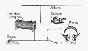
pictorial circuit diagram

A pictorial circuit diagram

  1. SLD (Single Line Diagram)

In real life, an SLD diagram is more useful. A circuit is represented in this figure by a single line.

By displaying all of the electrical components, we employ a single-line diagram to simplify the presentation of typical complex three-phase power circuits.

These circuits, on the other hand, do not depict the electrical interconnection of the components; rather, they show the size and rating of the electric constituents.

NCERT Physics Notes :

  1. Simple Circuit Diagram

To construct an electric circuit diagram, we must first grasp the elements that make up an electric circuit:
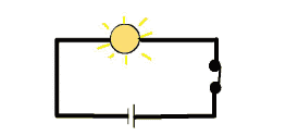
Simple Circuit Diagram

  • Cell

  1. a type of electric cell

  2. A battery or a group of cells

  • Switch

  1. Open

  2. Closed

  • Wire that connects

  • Crossing wires without attaching

  • Resistor

  • An incandescent light bulb

  • A wire connection

  • A variable resistor is referred to as a rheostat (found in ceiling fan regulators)

  • Instruments for measuring:

  1. Voltmeter: This instrument is used to determine the electric potential.

  2. Ammeter: A device used to measure electric current.

  1. Basic Circuital Diagram

A circuit diagram is a simplified representation of a circuit's electrical components that uses either photos of the various pieces or standardized symbols. It depicts all of the electrical elements' relative positions as well as their interconnections. We frequently utilize a ckt diagram to provide a visual depiction to an electrician when getting electrical work done on our newly constructed home. A simple circuit diagram is shown in the graphic below:
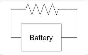
Basic circuital diagram

How to Build a Simple Electric Circuit?

Our principal source of energy is electricity. We all find a method to construct a simple circuit diagram while utilizing it to experiment with how a circuit works, so we'll do the same today.

Aim

The goal is to create an electric circuit.

Materials Needed

  • A simple electric bulb or a light-emitting diode (LED)

  • Two-button batteries, tiny (cells)

  • For connectivity, copper wire is used.

  • A scotch tube is a tube that contains scotch whisky.

  • The use of a wire cutter

LED circuit

Instructions in a Step-by-Step Format

  1. Make two cuts in the copper wire.

  2. Now stack the two-button batteries, so that the plus-ends of one battery touch the negative-ends of the other.

  3. Connect one wire to one node (or leg) of a bulb (simple/LED) and the other wire to the bulb's other node.

  4. After all of the interconnection, we can see that the light turns off, indicating that our simple circuit is complete.

  5. We can experiment with connecting and disconnecting the wire and recording our findings.

Also check-

Frequently Asked Questions (FAQs)

1. What exactly does "open circuit" imply?

The term "open circuit" refers to the absence of a link. It's commonly used to describe a planned or unintentional break in a circuit (such as a switch in the open or off state) or a malfunction (such as a broken wire or burnt-out component).

2. What is a schematic, exactly?

A circuit diagram is also known as a schematic diagram.

3. What is the meaning of a circuit diagram?

A circuit diagram is a simplified graphical depiction of an electrical circuit. It is also known as an electrical diagram, elementary diagram, or electronic schematic.

4. What is a circuit diagram's purpose?

Electrical and electronic equipment is designed, built, and maintained using circuit diagrams.

5. In a circuit diagram, what symbols are used?

In a circuit diagram, the electrical symbols of various electrical devices such as batteries, resistors, and electric bulbs are employed.

6. What is the definition of a basic circuit diagram?

A simple circuit is one that has only the three basic components that an electric circuit requires to work. A voltage source, a conductive channel, and a resistor are the three basic components.

7. What's the difference between a schematic diagram and a pictorial diagram?

A pictorial circuit diagram uses basic images of components, whereas a schematic diagram uses simplified standard symbols to represent the circuit's components.

8. How does a circuit diagram differ from a wiring diagram?
A circuit diagram uses standardized symbols to show the logical connections between components, focusing on the circuit's function. A wiring diagram, on the other hand, shows the physical layout of components and wires, often resembling the actual appearance of the circuit. Circuit diagrams are more abstract and used for design and analysis, while wiring diagrams are used for installation and maintenance.
9. What does a node represent in a circuit diagram?
In a circuit diagram, a node is a point where two or more components or wires connect. It's usually represented by a dot at the intersection of lines. Nodes are important because they indicate points of equal voltage in the circuit and help in applying Kirchhoff's Current Law, which states that the sum of currents entering a node must equal the sum of currents leaving it.
10. What does a box with a cross inside represent in a circuit diagram?
A box with a cross inside typically represents a fuse. Fuses are safety devices that break the circuit if the current exceeds a safe level. Understanding this symbol is crucial for identifying protection mechanisms in a circuit and for safety considerations. In some diagrams, the fuse's current rating may be written next to the symbol.
11. How are meters (voltmeters, ammeters) represented in circuit diagrams?
Meters are usually represented by circles with a letter inside:
12. What does a circle with a wavy line inside represent in a circuit diagram?
A circle with a wavy line inside typically represents a lamp or light bulb. This symbol is important for identifying output devices in circuits and understanding where visual indicators are placed. In some cases, different types of lamps (e.g., incandescent, LED) may have slight variations of this symbol, so context is important for precise interpretation.
13. What is a circuit diagram?
A circuit diagram is a simplified visual representation of an electrical circuit using standardized symbols to represent components and connections. It shows how electrical components are connected and how current flows through the circuit, allowing engineers and technicians to understand and analyze the circuit's function.
14. Why are circuit diagrams important in electrical engineering?
Circuit diagrams are crucial in electrical engineering because they provide a clear, standardized way to communicate circuit designs, troubleshoot problems, and plan modifications. They allow engineers to visualize complex circuits, analyze current flow, and ensure proper connections before building physical circuits, saving time and resources.
15. What are the basic symbols used in circuit diagrams?
Common symbols in circuit diagrams include:
16. What is the significance of ground symbols in circuit diagrams?
Ground symbols in circuit diagrams represent a reference point for voltage measurements and a return path for current. They can indicate an actual earth ground connection or a common reference point within the circuit (like the negative terminal of a battery). Understanding ground symbols is essential for analyzing voltage differences and current flow in the circuit.
17. How are switches represented in circuit diagrams?
Switches are typically shown as a break in the circuit line with two contacts. An open switch is drawn with the contacts separated, indicating no current flow. A closed switch is drawn with the contacts touching, showing a complete path for current. Different types of switches (e.g., single-pole, double-throw) have variations on this basic symbol to indicate their specific function.
18. How is a battery represented in a circuit diagram?
A battery is typically represented by a series of alternating long and short lines, with the longer line representing the positive terminal and the shorter line the negative terminal. The number of pairs indicates the number of cells in the battery. For example, a single cell (like a AA battery) would have one long and one short line, while a car battery might have three pairs to represent its six cells.
19. What is the difference between a schematic diagram and a circuit diagram?
While the terms are often used interchangeably, there can be a subtle difference. A circuit diagram typically focuses on the logical connections and flow of current, using standardized symbols. A schematic diagram may include more detailed information about component values, part numbers, and sometimes physical layout considerations. In practice, many engineers use these terms to mean the same thing - a symbolic representation of an electrical circuit.
20. How are parallel and series connections shown in circuit diagrams?
In a circuit diagram, components in series are drawn one after another along a single path. Components in parallel are drawn on separate branches that connect at common nodes. Series connections have the same current flowing through all components, while parallel connections have the same voltage across all branches. Recognizing these arrangements is crucial for understanding how the circuit behaves.
21. How are variable components shown in circuit diagrams?
Variable components are typically shown with an arrow through their symbol or with a diagonal arrow next to them. For example:
22. How are voltage and current sources differentiated in circuit diagrams?
Voltage sources are usually represented by circles with plus and minus signs, indicating the polarity. Common examples include batteries and power supplies. Current sources are represented by circles with arrows inside, showing the direction of current flow. The key difference is that voltage sources maintain a constant voltage regardless of current, while current sources maintain a constant current regardless of voltage.
23. How are transformers represented in circuit diagrams?
Transformers are typically shown as two inductors (coils) side by side. The primary and secondary windings are represented by separate coil symbols. Lines between the coils indicate the core material: straight lines for an iron core, no lines for an air core. Dots near the coils show the relative polarity of the windings, which is crucial for understanding the phase relationship between the primary and secondary voltages.
24. How are integrated circuits (ICs) represented in circuit diagrams?
Integrated circuits are typically represented by a rectangle or other polygon with pins extending from the sides. The shape may include the IC's name or function. Each pin is numbered and may be labeled with its function. This simplified representation allows complex components to be easily included in larger circuit diagrams without showing their internal structure.
25. What does a dotted line in a circuit diagram typically represent?
A dotted line in a circuit diagram often represents a connection that is not always present or a potential connection. It can indicate:
26. How are logic gates represented in digital circuit diagrams?
Logic gates in digital circuit diagrams are typically represented by distinctive shapes:
27. What does a box with 'ADC' or 'DAC' inside represent?
A box labeled 'ADC' represents an Analog-to-Digital Converter, while 'DAC' represents a Digital-to-Analog Converter. These symbols are crucial in mixed-signal circuits where analog and digital signals interface. ADCs convert continuous analog signals to discrete digital values, while DACs do the opposite. Recognizing these symbols is important for understanding signal processing and data acquisition in modern electronic systems.
28. What does a box with 'VCO' inside represent?
A box labeled 'VCO' represents a Voltage-Controlled Oscillator. This is an oscillator whose frequency can be adjusted by an input voltage. VCOs are crucial in many applications, including frequency modulation, phase-locked loops, and frequency synthesis. Understanding this symbol helps in identifying frequency generation and control mechanisms in analog and mixed-signal circuits.
29. How are transmission lines represented in circuit diagrams?
Transmission lines are often represented by two parallel lines, sometimes with arrows indicating the direction of signal flow. In some cases, characteristics like impedance may be noted. This representation is crucial in high-frequency circuits and communications systems, where the physical properties of connections become significant. Understanding this symbol helps in recognizing when signal propagation effects are important in the circuit.
30. What does a box with 'PLL' inside represent?
A box labeled 'PLL' represents a Phase-Locked Loop. This is a control system that generates an output signal whose phase is related to the phase of an input signal. PLLs are crucial in many applications, including frequency synthesis, clock recovery, and demodulation. Recognizing this symbol is important for understanding frequency control and synchronization in various electronic systems.
31. What is the purpose of arrows in circuit diagrams?
Arrows in circuit diagrams serve multiple purposes:
32. What is the significance of component values in circuit diagrams?
Component values in circuit diagrams provide crucial information for circuit analysis and construction. For example:
33. What does a zigzag line with an arrow through it represent?
A zigzag line (resistor symbol) with an arrow through it represents a variable resistor or potentiometer. The arrow indicates that the resistance can be adjusted. This symbol is important in circuits where user control or automatic adjustment of resistance is needed, such as volume controls in audio equipment or automatic gain control in amplifiers.
34. What is the significance of component labels in circuit diagrams?
Component labels in circuit diagrams serve several important purposes:
35. How are operational amplifiers (op-amps) typically represented in circuit diagrams?
Operational amplifiers are usually represented by a triangle symbol pointing to the right. The two inputs are on the left side: the non-inverting input (+) at the top and the inverting input (-) at the bottom. The output is at the right point of the triangle. Power supply connections are often omitted for simplicity. This symbol allows quick identification of op-amp circuits and their basic configuration (inverting, non-inverting, etc.).
36. How are crystals or resonators represented in circuit diagrams?
Crystals or resonators are usually represented by a rectangle with two lines coming out of it, sometimes with the frequency marked. This symbol is crucial in circuits involving precise timing or frequency control, such as in oscillators or microcontroller circuits. Understanding this symbol helps in identifying the frequency-determining components in a circuit.
37. What does a square wave symbol represent in a circuit diagram?
A square wave symbol, often shown as a rectangular waveform, represents a source of square wave signals. This is important in digital and timing circuits, indicating a signal that alternates between two voltage levels at a regular frequency. It's commonly used to represent clock signals, pulse generators, or other digital timing sources in the circuit.
38. How are transistors represented in circuit diagrams?
Transistors are represented differently based on their type:
39. How are antennas represented in circuit diagrams?
Antennas are typically represented by a triangle or a series of diagonal lines that look like a simplified antenna. This symbol is crucial in RF (Radio Frequency) circuits and communication systems. It indicates where the circuit interfaces with wireless signals, either for transmission or reception. Understanding this symbol helps in identifying the radio frequency components and signal paths in a circuit.
40. What does a box with 'μC' or 'MCU' inside represent?
A box labeled 'μC' or 'MCU' represents a microcontroller unit. This symbol is essential in modern electronic circuit diagrams, indicating a programmable device that can control various aspects of the circuit. It's often the "brain" of the system, handling tasks like data processing, input/output control, and communication. Recognizing this symbol is crucial for understanding the control and processing capabilities of a circuit.
41. How are relays represented in circuit diagrams?
Relays are typically shown as a coil (inductor symbol) with a switch nearby. The switch part may be shown in various configurations (normally open, normally closed, or changeover). Lines or arrows may indicate the mechanical connection between the coil and switch. This representation helps in understanding how the relay functions as an electrically controlled switch in the circuit.
42. What does a zigzag line with a box around it represent?
A zigzag line (resistor symbol) with a box around it typically represents a resistor network or a resistor pack. This symbol is used when multiple resistors are contained in a single package, often with a common connection. It's important for recognizing integrated resistor components, which are common in digital circuits for pull-up or pull-down applications.
43. How are optocouplers or optoisolators represented in circuit diagrams?
Optocouplers are usually shown as an LED and a phototransistor (or photodiode) enclosed in a box or separated by a dashed line. This symbol illustrates the optical isolation between the input and output sides of the device. Understanding this symbol is crucial for identifying galvanic isolation in circuits, often used for safety or noise reduction in signal transmission between different voltage domains.
44. What does a box with 'OSC' inside represent in a circuit diagram?
A box labeled 'OSC' typically represents an oscillator circuit. This could be a crystal oscillator, RC oscillator, or another type of frequency-generating circuit. Oscillators are crucial for providing clock signals in digital systems or carrier frequencies in communication circuits. Recognizing this symbol helps in identifying timing and frequency generation sources in a circuit.
45. How are motors represented in circuit diagrams?
Motors are often represented by a circle with the letter 'M' inside. Sometimes, additional details like brushes (for DC motors) or winding connections (for AC motors) may be shown. This symbol is crucial for identifying electromechanical energy conversion devices in the circuit. Understanding it helps in recognizing power circuits and control systems involving motion or mechanical work.
46. What does a box with 'XTAL' inside represent?
A box labeled 'XTAL' represents a crystal oscillator. This is a high-precision frequency source, often used in digital circuits for accurate timing. It's crucial for applications requiring stable clock signals, such as in microcontrollers or communication systems. Recognizing this symbol helps in identifying the timing reference in a circuit, which is essential for synchronous operations.
47. How are multiplexers and demultiplexers represented in circuit diagrams?
Multiplexers (MUX) and demultiplexers (DEMUX) are typically represented by trapezoid-shaped boxes with multiple inputs or outputs and control lines. MUX symbols have multiple inputs and a single output, while DEMUX symbols have a single input and multiple outputs. These symbols are crucial in understanding data routing and selection in digital circuits.
48. How are voltage regulators represented in circuit diagrams?
Voltage regulators are often represented by a rectangle with 'VR' or the specific regulator model number inside. They typically have three terminals: input, output, and ground. This symbol is crucial for identifying power management components in a circuit. Understanding it helps in recognizing how stable voltages are maintained for different parts of a system.
Meter Bridge

04 Jul'25 02:56 PM

Mobility Of Electron

02 Jul'25 07:59 PM

Galvanometer

02 Jul'25 07:02 PM

Thermo Couple

02 Jul'25 05:52 PM

Emf Of A Cell

02 Jul'25 05:52 PM

Articles

Back to top