Potentiometer - Principle And Applications
A potentiometer is an adaptable tool used to find out and also compare electricity potentials- mostly in DC currents. Basically, it operates under the assumption that voltage drop on a constant length of wire varies uniformly with its length provided there is a constant current flowing through it, therefore, allowing accurate measurement and not requiring withdrawal of power from the test setup.
In this article, we will discuss the concept of Potentiometer - Principle And Applications. It is an essential gadget in the learning of current electricity which is important for Class 12, NEET and JEE Main exams. Over the last ten years of the JEE Main exam (from 2013 to 2023), a total of fifteen questions have been asked on this concept. And for NEET seven questions were asked from this concept.
What is a Potentiometer?
The potentiometer is a device which does not draw current from the given circuit and still measures the potential difference. It is a device used to measure the e.m.f of a given cell and to compare the e.m.f of cells. It is also used to measure the internal resistance of a given cell

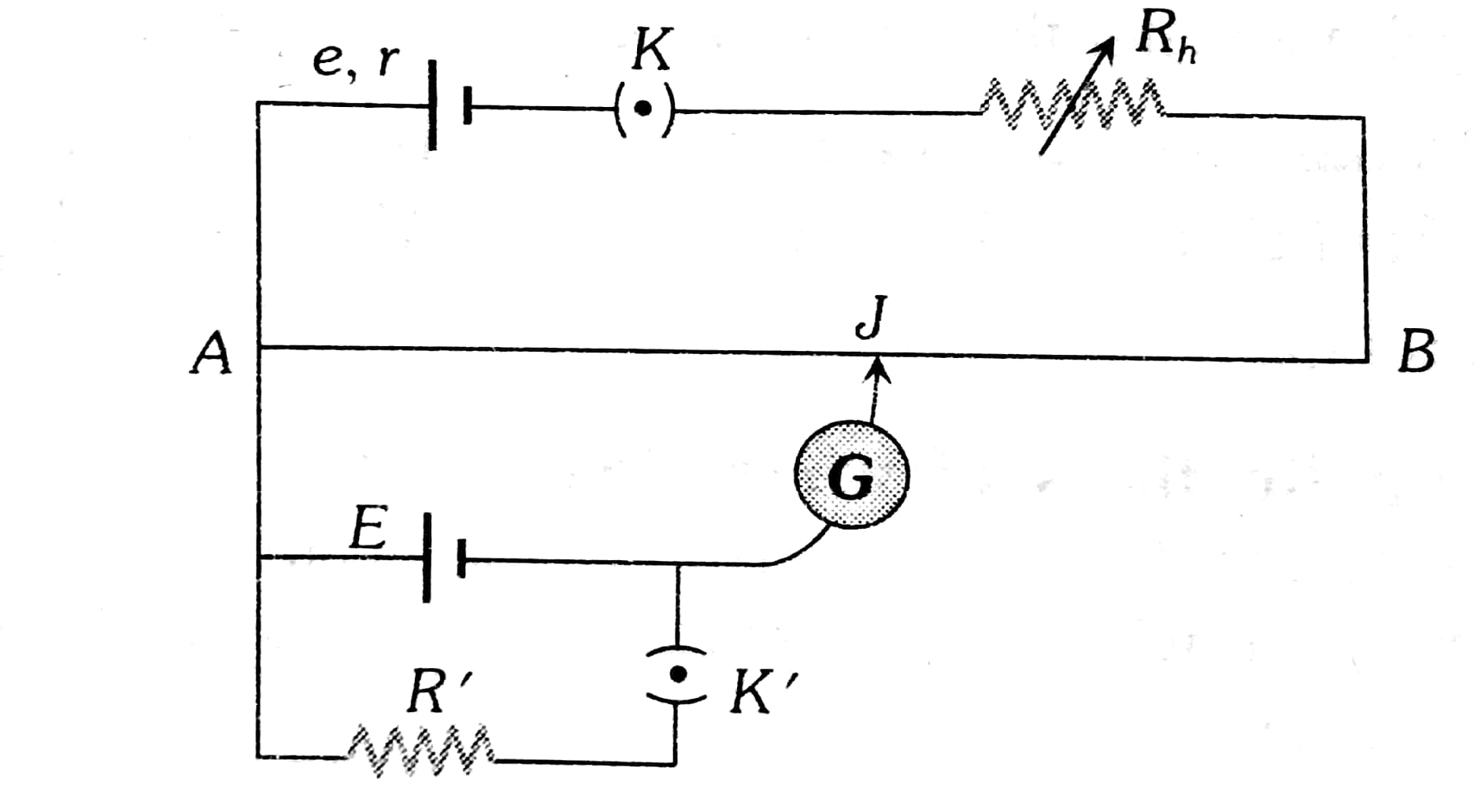
The potentiometer consists of wires of length 5 to 10 meters arranged on a wooden block as parallel strips of wires with 1-meter length each and the ends of wires are joined by thick coppers. The wire has a uniform cross-section and is made up of the same material. A driver circuit that contains a rheostat, key, and a voltage source with internal resistance r. The driver circuit sends a constant current (I) through the wire.
The potential across the wire AB having length L is given as V=IR, Where R is the resistance of the wire AB
Since the driver circuit sends a constant current (I) through the wire So
Using
Therefore we get V is proportional to length. I.e
The secondary circuit contains cells/resistors whose potential is to be measured. One end is connected to a galvanometer and another end of the galvanometer is connected to a jockey which is moved along the wire to obtain a point where there is no current through the galvanometer. So the potential of the secondary circuit is proportional to the length at which there is no current through the galvanometer. This is how the potential of a circuit is measured using the potentiometer.
Calibration of Potentiometer

In the potentiometer, a battery of known emf E is connected to the secondary circuit. A constant current I is flowing through AB from the driver circuit (that is the circuit above AB). The jockey is slide on potentiometer wire AB to obtain null deflection in the galvanometer. Let l be the length at which the galvanometer shows null deflection.
Since the potential of wire AB (V) is proportional to the length AB(L).
So we get
Thus we obtained the potential of wire AB when a constant current is passing through it. This is known as calibration.
Potential Gradient
The potential difference per unit length of wire i.e
or Using

For the above figure
So since
With the help of the above ratio, we can compare the emf of these cells.
Determine the Internal Resistance of a Cell

Note- The cell in the secondary circuit has emf E and internal resistance r
Here
Similarly,
And we know that
or we can say that
So taking the ratio of equation (1) to equation (2), we get
Then the internal resistance is given by
Comparison of Resistances

The balance point is at a length l1 cm from A when jockey J is plugged in between Y and X, while the balance point is at a length l2 cm from A when jockey J is plugged in between Y and Z.
Then we get a ratio of resistances as
With the help of this ratio, we can compare these resistances.
Solved Examples Based on Potentiometer - Principle And Applications
Example 1: In the given circuit of the potentiometer, the potential difference E across AB (10 m length) is larger than E1 and E2 as well. For key K1 (closed), the jockey is adjusted to touch the wire at J1 so that there is no deflection in the galvanometer. Now the first battery (E1) is replaced by the second battery (E2) for working by making K1 open and K2 closed. The galvanometer gives them a null deflection at J2. The value of

1) 1
2) 2
3) 3
4) 4
Solution:
Length of AB=10 m
For battery
For battery
Now, we know that
Hence, the answer is option (1).
Example 2: In the given potentiometer circuit arrangement, the balancing length AC is measured to be 250 cm. When the galvanometer connection is shifted from point (1) to point (2) in the given diagram, the balancing length becomes 400 cm. The ratio of the emf of two cells \frac{\varepsilon_1}{\varepsilon_2} is :

1)
2)
3)
4)
Solution:
When the galvanometer is connected to the point (1)
When the galvanometer is connected to point (2)
Where
Hence, the answer is option (1).
Example 3: A DC main supply of e.m.f.
1) 11
2) 9
3) 7
4) 0
Solution:
Given
Hence, the answer is (1).
Example 4: In a potentiometer experiment the balancing with a cell is at a length
1) 7
2) 2
3) 1
4) 0.5
Solution:
Determine the internal resistance
wherein
The internal resistance of a cell is given by
Hence, the answer is option (2).
Example 5: The balancing length for a cell is
resistance of the cell is 10 , where
1) 21
2) 24
3) 12
4) 42
Solution:
Hence, the answer is option (2).
Summary
A potentiometer is a gadget customarily utilized for ascertaining the potential difference (voltage) over a component in a circuit without sourcing any current from that particular element. It works based on the fact the loss of potential over a length of wire is directly proportional to that length. By employing a sliding contact along the wire with the intention of comparing an unknown voltage to a given reference electrical potential point the unknown voltage could be found precisely.
Frequently Asked Questions (FAQs)