Kirchhoff’s Law - Equation, Example, FAQs
Kirchhoff’s circuit laws are fundamental for analyzing electrical circuits. Using these laws along with the equations for Active and passive elements like resistors, capacitors and inductors, we can effectively study the behavior of complex circuits. There are two Kirchoff's laws- Kirchoff's first law also called Kirchoff's current law and Kirchoff's second law which is also called Kirchoff's voltage law. These are applicable to DC as well as AC currents. In this article, we will discuss state Kirchhoff's current law and Kirchhoff's current law formula, state and explain Kirchhoff's voltage law and Kirchhoff's voltage law formula, advantages of Kirchhoff's law and limitations of Kirchhoff's law.
This Story also Contains
- Overview Of Gustav Robert Kirchoff and His Circuital Laws
- What Are Kirchhoff’s Laws?
- Kirchhoff’s First Law or Kirchhoff’s Current Law (KCL LAW)
- Kirchhoff’s Second Law or Kirchhoff’s Voltage Law (KVL LAW)
- Applications of Kirchhoff’s Laws
- Limitations of Kirchhoff’s laws
- Solved Example Based on Kirchhoff's Laws

Also read:
Overview Of Gustav Robert Kirchoff and His Circuital Laws
Kirchhoff's circuit rules are two equalities that deal with the electric current and potential difference in the lumped element model of electrical circuits (often known as voltage).In 1845, a German scientist named Gustav Robert Kirchhoff was the first to describe them. This broadened Georg Ohm's work and came before James Clerk Maxwell's. Kirchhoff's rules, often known as Kirchhoff’s laws, are widely utilized in electrical engineering. These rules apply in both time and frequency domains and serve as the foundation for network analysis.
Kirchhoff’s current law (KCL LAW) and Kirchhoff’s voltage law (KVL LAW) were defined in 1845 after he pursued the notions of Ohm's law and Maxwell's law.
Kirchhoff’s current law, or KCL LAW, is based on the principle of electric charge conservation. The input current to a node must be equal to the node's output current, according to this rule.
What Are Kirchhoff’s Laws?
In 1845, German physicist Gustav Kirchhoff introduced two important laws that explain how current and energy are conserved in electrical circuits. These are known as Kirchhoff’s Current Law (KCL) and Kirchhoff’s Voltage Law (KVL). They are very useful for analyzing complex electrical networks and finding unknown currents and voltages.
- Kirchhoff’s Current Law (KCL): Also called the Junction Rule or First Law, it states that the total current entering a junction equals the total current leaving the junction. This follows the law of conservation of charge.
- Kirchhoff’s Voltage Law (KVL): Also called the Loop Rule or Second Law, it states that the sum of all voltages around a closed loop is zero. This follows the law of conservation of energy.
Kirchhoff’s First Law or Kirchhoff’s Current Law (KCL LAW)
Kirchhoff’s current law definition: - The current coming into a node (or a junction) must match the current flowing out of it, according to Kirchhoff's first law. This is due to charge conservation.
The conventional technique to explain Kirchhoff’s current law is to write Kirchhoff’s equation in which the sum of all currents entering the junction equals the sum of currents exiting the junction.
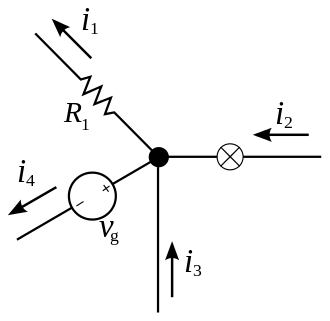
From the figure, the circuit consists of a junction with four branches. Currents $i_1, i_2, i_3$, and $i_4$ flow through these branches, involving a resistor $R_1$, a voltage source $V_g$, and other components. Kirchhoff's Current Law can be applied at the junction to relate the incoming and outgoing currents.
The current that enters a junction equals the current that leaves that junction.
$i_1+i_4=i_2+i_3$
This can be generalized to n wires joined together at a node, so Kirchhoff's current law formula is given as,
$
\sum_{k=1}^n i_k=0
$
Kirchhoff’s Second Law or Kirchhoff’s Voltage Law (KVL LAW)
Kirchhoff’s voltage law definition: - The sum of all voltages across components that supply electrical energy (such as cells or generators) in any entire loop inside a circuit must match the sum of all voltages across all other components in the same loop, according to Kirchhoff’s voltage law (2nd Law). This law is the result of both charge and energy conservation.
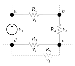
When there are multiple junctions in a circuit, we must be careful to apply this law to only one loop at a time. In practice, this means selecting only one option at each crossroads. In the diagram given below, the circuit is a closed loop consisting of resistors $R_1, R_2, R_3$, and $R_5$ connected between nodes $a, b, c, d$, along with a voltage source $V_4$ between nodes $a$ and $d$. The currents flow through the resistors and are governed by the voltage drops $v_1, v_2, v_3$, and $v_5$ across each resistor, as determined by Kirchhoff's Voltage Law.
The total of all voltages around a loop equals zero.
$v_1+v_2+v_3+v_4=0$
Kirchhoff’s voltage law formula can be generalized.
$\sum_{k=1}^n V_k=0$
Applications of Kirchhoff’s Laws
Kirchhoff’s laws are widely used in electrical and electronic circuit analysis. Some important applications are:
- Complex Circuit Analysis: Used to calculate current and voltage in circuits with multiple loops and junctions.
- Bridge Circuits: Applied in Wheatstone bridges to determine unknown resistances.
- Electrical Networks: Helps in analyzing series-parallel networks and finding equivalent resistances.
- AC and DC Circuits: Used in both alternating current (AC) and direct current (DC) circuits for calculating currents, voltages, and impedances.
- Electronics Design: Useful in designing amplifiers, filters, and electronic devices by analyzing current flow and voltage drops.
Limitations of Kirchhoff’s laws
Both Kirchhoff’s laws contain a constraint in that they work under the premise that the closed loop has no fluctuating magnetic field. In the presence of a fluctuating magnetic field, electric fields, and emf can be induced, causing Kirchhoff’s loop rule to fail.
Other limitations are:
- Applicable to lumped circuits only
- High-frequency limitations
- Difficult for complex circuits
Recommended Topic Video
Solved Example Based on Kirchhoff's Laws
1. Consider a circuit with a 12 V battery and two resistors, $R_1=4 \Omega$ and $R_2=6 \Omega$, connected in parallel. Find the current through each resistor using Kirchhoff's Current Law (KCL) and Kirchhoff's Voltage Law (KVL).
Solution:
Using KVL
In parallel circuits, the voltage across each resistor is equal to the battery voltage:
$
V_1=V_2=12 \mathrm{~V}
$
Using Ohm's Law (from KVL)
$
\begin{aligned}
& I_1=\frac{V}{R_1}=\frac{12}{4}=3 \mathrm{~A} \\
& I_2=\frac{V}{R_2}=\frac{12}{6}=2 \mathrm{~A}
\end{aligned}
$
Using KCL at the junction
The total current supplied by the battery is the sum of branch currents:
$
I_{\text {total }}=I_1+I_2=3+2=5 \mathrm{~A}
$
Related Topics,
- Difference Between Resistance and Resistivity
- Electrical Energy and Power
- Electrical Resistance
- Electromotive Force
- Ohm's Law
Frequently Asked Questions (FAQs)
Kirchhoff’s equations allow us to determine unknown currents and voltages in a circuit, ensuring the conservation of charge and energy. They are fundamental for circuit analysis and design.
Kirchhoff’s laws may not be accurate at very high frequencies where electromagnetic radiation, capacitance, and inductance effects dominate, or in non-lumped circuits where voltage and current are not uniform.
Kirchhoff’s laws are used to analyze complex electrical circuits, calculate currents and voltages, solve bridge circuits, and design electronic devices. They are applicable in both AC and DC circuits.
The electric energy gained within a closed electrical circuit is likewise lost within the loop, according to the law of conservation of energy. In a closed circuit, the sum of potential differences will also be zero.
The most common question for a newcomer in circuit theory is "assert Kirchhoff’s current law." Kirchhoff's first law, often known as Kirchhoff's current rule, asserts that within a node, no charge is lost. As a result, the charge entering the node, or current incoming, is equal to the charge exiting the same node, or current outgoing. When several conductor branches intersect at a node, the total sum of charge or current surrounding the node is zero. A sign convention is usually followed during a circuit analysis.
Kirchhoff’s laws are applicable to both direct current and alternating current circuits. They can be used accurately for both DC and low-frequency AC circuits.
Kirchhoff’s law can be found in single loop circuits, complicated electrical circuits, and charging circuits. This law can be seen in closed-loop circuits.
Kirchhoff's rules have a wide range of applications, but they also have a number of drawbacks and restrictions. To begin with, many complex circuits necessitate extensive analysis. Kirchhoff's rules make it easier to simplify these circuits and determine unknown currents and voltages. These laws can be used for the practical analysis of any electrical circuit. But, like with anything, there are advantages and disadvantages. Kirchhoff’s law, however, has a number of drawbacks and limits. Kirchhoff’s law has a severe flaw in that it implies the closed-loop has no variable magnetic field. In the circuit, induction of emf or any electric fields is conceivable. The current and voltage rule will eventually fail as a result of this. KCL LAW has an impact on high-frequency circuits as well. Another problem is that KCL LAW is only valid and usable if the entire electric charge inside the circuit is constant.