Derivation of Lens Formula - Definition, FAQs
Lenses are pieces of curved glass or some transparent material, and they bend light to create images. Lenses are commonly found in cameras, eyeglasses, microscopes and telescopes. The formation of an image by lenses is understood with the help of the lens formula, a mathematical expression that relates the object distance (u), image distance (v), and focal length (f) of a lens. In this article, we shall derive the lens formula step by step using simple ray diagrams and basic geometry, all for the benefit of a simple-to-understand concept for students and for application to numerical problems.
This Story also Contains
- What Is A Lens?
- What is the Lens Formula?
- Lens Formula Derivation
What Is A Lens?
The lens is a transparent object that may be made of glass or plastic, and it bends (or refracts) light rays to create images. These are lenses with curved surfaces that primarily use the principle of refraction. Lenses are found in eyeglasses, cameras, microscopes, and magnifying glasses.
Lenses are based on two basic types:
- Convex lens (converging lens): Thicker in the middle, bending light rays to bring them together, and can create real or virtual images.
- Concave lens (diverging lens): Thinner in the middle, diverging light rays, and always forming a virtual image.
The lens is divided into two types depending on how the light rays behave when they travel through the lens. These are further divided into the following types.
.png)
Commonly Asked Questions
The lens formula is fundamental in understanding how the human eye forms images. It helps explain how the eye's lens changes shape (accommodation) to focus on objects at different distances, effectively changing its focal length to maintain a clear image on the retina. This application of the formula is crucial in optometry and ophthalmology.
The lens formula, while not directly involving nodal points, helps in understanding their significance. Nodal points are locations where light rays entering and exiting the lens appear to have no angular deviation. The formula's assumption of a thin lens approximates the two nodal points as coinciding at the lens's center, simplifying calculations for image formation.
Yes, the lens formula can explain this phenomenon. For a concave lens, f is negative. When dealing with a real object (positive u), the formula 1/v = 1/f - 1/u always results in a negative v, indicating a virtual image. This mathematical result aligns with the physical reality that concave lenses diverge light rays, forming virtual images for real objects.
The lens formula helps define focal planes in optical systems. The focal plane is where objects at infinity form their images, which occurs when 1/u approaches zero in the formula. This simplifies to v = f, defining the focal plane's location. Understanding this relationship is crucial in designing complex optical systems like cameras and telescopes.
While the lens formula doesn't directly calculate depth of field, it's fundamental to understanding it. The formula shows how slight changes in object distance (u) affect image distance (v). In photography, depth of field refers to the range of object distances that appear acceptably sharp. The lens formula helps explain why larger apertures (shorter effective f) result in a shallower depth of field.
What is the Lens Formula?
The lens equation or lens formula is an equation that links the focal length, image distance, and object distance.
$\frac{1}{v}-\frac{1}{u}=\frac{1}{f}$
where,
v is the distance of the image from the optical centre of the lens, u is the distance of the object from the optical centre of the lens and f is the focal length of the lens.
Also read-
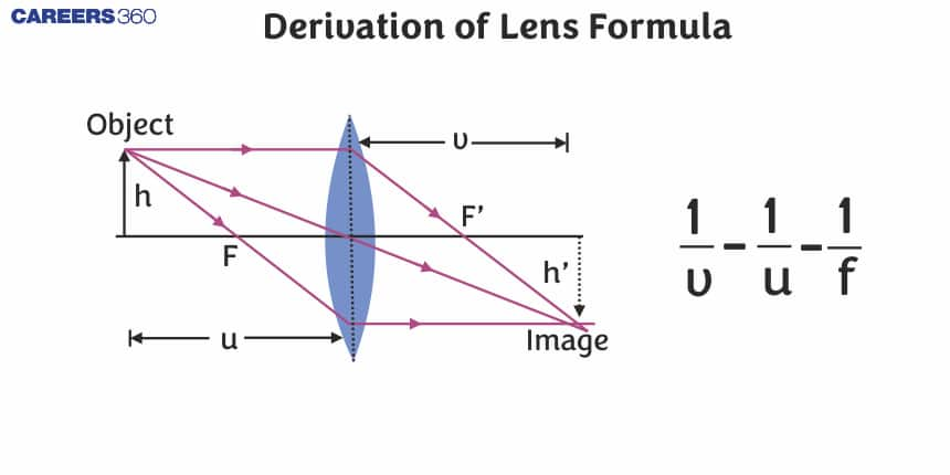
Lens Formula Derivation
Let AB represent an object at a distance greater than the focal length f of the convex lens that is located at right angles to the primary axis. The image A' B' is generated between O and $F_1$ on the same side as the item, and it is virtual and erect.
.png)
- Focul length = $OF_1$ = f
- Object distance = OA =u
- Image distance = $OA_1$ = v
$\triangle O A B$ and $\triangle$ O A' B' are similar
\begin{array}{l}\because \angle B A O=\angle B^1 A^1 O=90^{\circ}, \text { vertex is common for both the triangles } \\ \text { so } \angle A O B=\angle A^1 O B^1, \therefore \angle A B O=\angle A^1 B^1 O\end{array}
$\frac{A' B'}{A B}=\frac{O A'}{O A}---(1)$
$\triangle O C F_1$ and $\triangle F_1 A' B' $ are similar
$\frac{A' B'}{O C}=\frac{A' F_1}{O F_1}$
But from the ray diagram, we see that OC = AB
$\begin{aligned} & \frac{A' B'}{A B}=\frac{A' F_1}{O F_1}=\frac{O F_1-O A'}{O F_1} \\ & \frac{A' B'}{A B}=\frac{O F_1-O A'}{O F_1}---(2)\end{aligned}$
From equation (1) and equation (2), we get
$\begin{aligned} & \frac{O A'}{O A}=\frac{O F_1-O A'}{O F_1} \\ & \frac{-v}{-u}=\frac{-f--v}{-f} \\ & \frac{v}{u}=\frac{-f+v}{-f} \\ & -v f=-u f+u v\end{aligned}$
Dividing throughout by uvf
$-\frac{1}{u}=-\frac{1}{v}+\frac{1}{f}$
$\frac{1}{f}=\frac{1}{v}-\frac{1}{u}$
Read more-
Frequently Asked Questions (FAQs)
The lens formula is directly related to lens power addition. Since lens power is defined as P = 1/f, the formula can be rewritten in terms of power: P = 1/u + 1/v. This additive nature of lens powers is crucial in optometry, especially when combining lenses (like in bifocals) or calculating the total power of a lens system.
Yes, the lens formula explains this versatility of convex lenses. For objects beyond the focal point (u > f), the formula yields a positive v, indicating a real image. For objects within the focal length (u < f), v becomes negative, indicating a virtual image. This mathematical behavior aligns with the physical reality of how convex lenses interact with light rays at different object distances.
The lens formula is fundamental in calculating hyperfocal distance - the closest distance at which a lens can be focused while keeping objects at infinity acceptably sharp. By manipulating the formula and incorporating the concept of circle of confusion, photographers can determine the optimal focus setting to maximize depth of field, a crucial technique in landscape and architectural photography.
The lens formula shows that for real images to form (positive v), the term 1/u must be smaller than 1/f for convex lenses (positive f). This mathematically demonstrates that real images can only form when the object is beyond the focal point, revealing the crucial relationship between focal length and real image formation.
The lens formula helps explain depth of focus, which is related to depth of field but on the image side of the lens. Lenses with longer focal lengths (smaller 1/f) have a shallower depth of focus. This is because small changes in object distance (u) result in larger changes in image distance (v) for lenses with longer focal lengths, as evident from the formula's relationships.
Telecentric lenses are designed so that the chief rays are parallel to the optical axis in object or image space. While the basic lens formula doesn't directly describe telecentricity, it forms the foundation for understanding how these lenses work. By manipulating the object or image distance to approach infinity, we can create conditions where magnification becomes independent of object position, a key feature of telecentric systems.
In microscopy, the working distance is the space between the objective lens and the specimen. The lens formula helps understand how changing this distance (effectively changing u) affects the image formation. It shows that as the working distance decreases (smaller u), the image distance (v) increases, which relates to the magnification and the design of microscope objectives.
Yes, the lens formula helps explain this. For concave lenses (negative f), the formula always yields a negative v for positive u, indicating a virtual image. The magnification m = -v/u is always positive in this case, meaning the image is upright. This mathematical result aligns with the physical behavior of concave lenses diverging light rays.
While the lens formula doesn't directly calculate field of view, it helps explain the relationship. A shorter focal length (larger 1/f) allows objects at a given distance to form images closer to the lens. This geometrically translates to a wider field of view. Conversely, longer focal lengths result in narrower fields of view, a principle crucial in understanding lens selection in photography and telescope design.
The lens formula, combined with the magnification equation (m = -v/u), reveals that the maximum theoretical magnification occurs as the object approaches the focal point. As u approaches f, v approaches infinity, and the magnification (v/u) becomes very large. However, practical limitations prevent achieving infinite magnification, illustrating the theoretical limits of single-lens systems.