Actions Of Transistors - PNP & NPN Transistor

Actions Of Transistors - PNP & NPN Transistor

Edited By Vishal kumar | Updated on Jul 02, 2025 05:09 PM IST

A transistor is referred to as a semiconductor device that amplifies or switches power and electrical signals. Transistor is the fundamental component of electronics. It is made of semiconductor material and typically has three terminals for connecting to an electronic circuit. The current flowing through alternate pairs of transistor terminals is controlled by the voltage or current provided to one set of those terminals. A transistor can boost a signal because the controlled(output) power is higher than the controlling (input) power. The majority of transistors are made of extremely pure silicon, while some are also made of germanium. However, other semiconductor materials are also occasionally used. In field-effect transistors, a transistor may only have one type of charge carrier, but bipolar junction transistor devices may have two types of charge carriers. Numerous manufacturers produce various transistor types following defined criteria.

This Story also Contains
  1. Working Of Transistor
  2. Types Of Transistors
  3. PNP Transistor In Detail
  4. Working Of The PNP Transistor
  5. NPN Transistor In Detail
  6. Working Of NPN Transistor
Actions Of Transistors - PNP & NPN Transistor

Working Of Transistor

To study the working of the transistor, one needs to be aware of the different parts of the transistor: Three layers of semiconductor materials named as terminals, are typically found in a transistor. These layers work together to connect the transistor to an external circuit and carry current. The current flowing through the alternate pair of terminals of a transistor is controlled by the voltage or current applied to either one of the terminal pairs. For a transistor, there are three terminals such as:

  • Base: The transistor is turned on with this.

  • Collector: This is the transistor's positive lead.

  • Emitter: The transistor's negative lead is the emitter.

The operation of transistors:

A transistor contains two P-N junctions and functions as a current-driven device.

There are two P-N junctions: one between the emitter and the base region and the other between the collector and the base region. A rather significant current flow through the device from the emitter to the collector can be controlled by a very modest current flow through the emitter to the base. The base-collector junction is biased in the opposite direction from the base-emitter junction. The collector circuit will experience current flow when a current passes through the base-emitter junction.

Types Of Transistors

There are primarily two sorts of transistors, depending on how they are employed in a circuit.

1. Bipolar junction transistor(BJT)-

The base, emitter, and collector are the three terminals of a BJT. A smaller current flow between the base and the emitter can control a bigger current flow between the collector and the emitter terminal.

There are also two varieties of BJT. These contain:

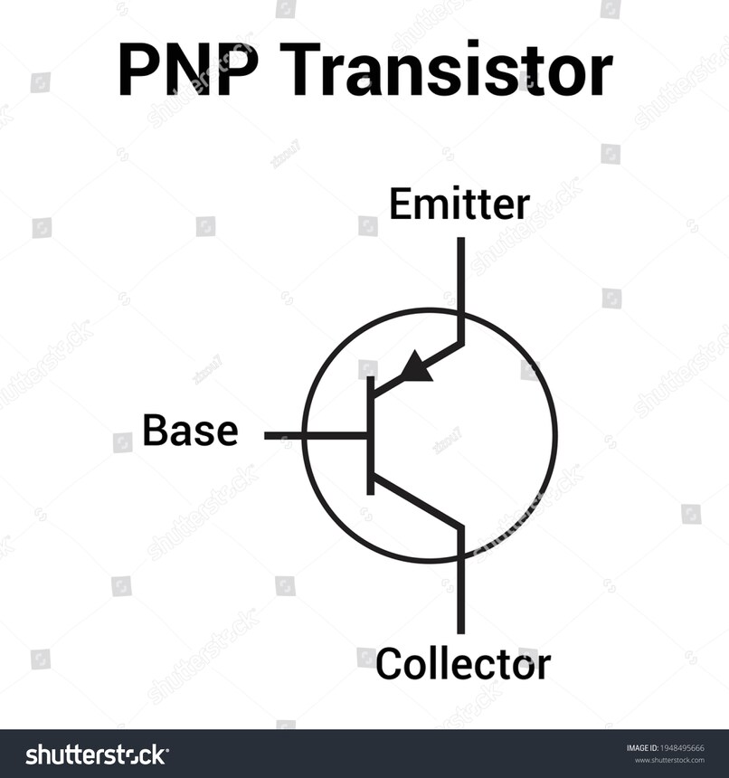
  • A P-N-P transistor is a particular kind of Bipolar junction transistor in which one n-type material is inserted between two p-type materials. The device will regulate the flow of electricity in such a setup. Two crystal diodes are linked in series to form the PNP transistor. The collector-base diode and emitter-base diode, respectively, are located on the diodes' right and left sides.

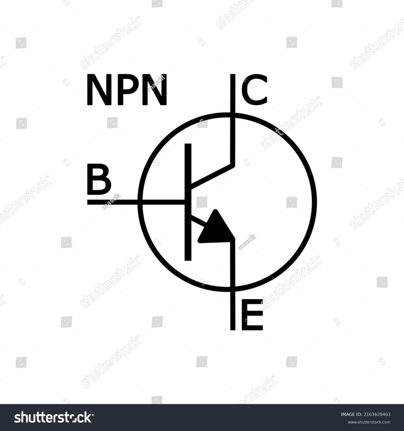
  • N-P-N Transistor: This transistor contains two n-type materials and one p-type material sandwiched in between. The main purpose of the N-P-N transistor is to amplify weak signals into powerful signals. In an NPN transistor, current forms in the transistor as electrons flow from the emitter to the collector region.

NEET Highest Scoring Chapters & Topics
This ebook serves as a valuable study guide for NEET exams, specifically designed to assist students in light of recent changes and the removal of certain topics from the NEET exam.
Download E-book

2. Field Effect transistor (FET)-

The gate, Source, and Drain are the three FET terminals. A current between the source and drain can be managed by the voltage at the gate terminal. A field effect transistor is a unipolar transistor that conducts electricity using either an N-channel FET or a P-channel FET. FETs are primarily used in analogue switches, buffer amplifiers, and low-noise amplifiers.

PNP Transistor In Detail

As we have discussed earlier, An N-type and two P-type semiconductors are sandwiched together to create a PNP transistor, which is a sort of bipolar junction transistor. The PNP transistor is represented by the symbol in the illustration below. The arrowhead depicts the direction of the current flow from the Emitter to the Collector.

1706262547328

Working Of The PNP Transistor

Three terminals make up a PNP transistor: the Collector (C), Emitter (E), and Base (B). When two PN junction diodes are connected back to back, the PNP transistor functions like that. The negative terminal of a voltage source (VEB) is linked to the Base terminal (N-type), while the positive terminal is connected to the Emitter(P-type). The Emitter-Base connection is therefore wired in forward bias. Additionally, a voltage source's positive terminal (VCB) is coupled with the N-type base terminal, while the negative terminal is coupled with the collector terminal (P-type). Consequently, reverse bias is applied to the Collector-Base junction. The depletion region at the emitter-base junction is constrained due to this sort of bias because it is coupled in the direction of forward bias. The depletion region at the Collector-Base junction is wide because of the reverse bias at the Collector-Base junction.

NPN Transistor In Detail

A P-type semiconductor is sandwiched between two N-type semiconductors to create an NPN transistor, which is the most popular type of bipolar junction transistor. The NPN transistor's symbol is depicted in the figure below. The arrowhead depicts the collector current (IC), base current (IB), and emitter current (IE) in their typical directions.

1706262541046

Working Of NPN Transistor

There are two junctions and three terminals in an NPN transistor. In a forward bias condition, supply voltage (VEE) connects the base-emitter junction. Additionally, supply voltage (VCC) connects the collector-base junction when it is in a reverse bias condition. The N-type semiconductor's negative supply source terminal (VEE) is connected in the forward bias condition (Emitter). Similarly, in a reverse bias condition, the N-type semiconductor is linked to the positive terminal of the supply source (VCC) (Collector). Electrons make up the majority of the charge carriers in N-type emitters. As a result, electrons begin to flow from an N-type emitter to a P-type base, where they continue to flow. A P-type semiconductor makes up the base. Base current ( IB) is the current that flows through the circuit as a result of the recombination.

Frequently Asked Questions (FAQs)

1. What is the working principle of a transistor?

The very fundamental operation of a transistor is to regulate the strength of a very little current passing through a second channel to control the flow of current through one channel.

2. List some characteristics of transistors.

Plots that can show the relationship between a transistor's current and voltage in a specific arrangement are called transistor characteristics.

  • Input characteristics: By keeping the output voltage constant, it will provide information on how the input current changes when the input voltage varies. 

  • Output characteristics: By maintaining a constant input current, this plot compares the output current to the output voltage. 

  • Characteristics of the current transfer: By maintaining a constant voltage, this plot illustrates how the output current varies with the input current.

3. Give some advantages of transistors.
  • smaller and less expensive. 

  • less sensitive mechanically. 

  • functioning at a low voltage. 

  • extraordinary longevity. 

  • No energy is used. 

  • switching quickly. 

  • Circuits with higher efficiency can be created.

4. What are the limitations of transistors?
  • Higher electron mobility is absent from transistors. 

  • As a result of electrical and thermal events, transistors are readily destroyed. Consider treating electrostatic discharge as an example. 

  • Radiation and cosmic rays have an impact on transistors.

5. How does the structure of an NPN transistor differ from a PNP transistor?
An NPN transistor consists of a thin P-type semiconductor layer (base) sandwiched between two N-type layers (emitter and collector). A PNP transistor has the opposite arrangement, with a thin N-type layer (base) between two P-type layers (emitter and collector). This structural difference affects the direction of current flow and the transistor's behavior in circuits.
6. What is the difference between forward-active and reverse-active modes in a transistor?
In forward-active mode, the base-emitter junction is forward-biased, and the base-collector junction is reverse-biased. This is the normal operating mode for amplification. In reverse-active mode, these biases are swapped: the base-emitter junction is reverse-biased, and the base-collector junction is forward-biased. Reverse-active mode is rarely used in practical circuits as it offers poor performance.
7. How does temperature affect transistor performance?
Temperature significantly affects transistor performance. As temperature increases, the current gain (β or hFE) of the transistor typically increases, which can lead to thermal runaway if not properly managed. Additionally, leakage currents increase with temperature, potentially causing unwanted behavior in circuits. Proper thermal management is crucial for stable transistor operation.
8. What is the role of the emitter in a transistor?
The emitter in a transistor is typically the most heavily doped region. Its primary role is to emit charge carriers (electrons in NPN, holes in PNP) into the base region. The emitter-base junction is usually forward-biased, allowing for easy injection of these carriers. The efficiency of this emission process greatly affects the overall performance and gain of the transistor.
9. What is the Early effect in transistors?
The Early effect, named after James Early, is a phenomenon in bipolar junction transistors where the effective width of the base region narrows as the reverse bias on the collector-base junction increases. This leads to an increase in the collector current and a corresponding decrease in the output resistance of the transistor, affecting its amplification characteristics.
10. How does minority carrier injection affect transistor operation?
Minority carrier injection is fundamental to bipolar transistor operation. When the base-emitter junction is forward-biased, minority carriers (electrons in PNP, holes in NPN) are injected from the emitter into the base. Most of these carriers diffuse across the base and are collected by the collector, forming the collector current. The efficiency of this injection and collection process directly affects the transistor's current gain and overall performance.
11. What is the importance of the transistor's safe operating area (SOA)?
The safe operating area (SOA) defines the voltage and current limits within which a transistor can operate safely without risk of damage. It's typically represented as a graph showing the maximum allowable collector current versus collector-emitter voltage. Operating outside the SOA can lead to thermal runaway, second breakdown, or other failure modes. Understanding and respecting the SOA is crucial for reliable circuit design, especially in power applications.
12. How does carrier recombination in the base region affect transistor efficiency?
Carrier recombination in the base region occurs when injected minority carriers recombine with majority carriers before reaching the collector. This process reduces the number of carriers contributing to the collector current, thereby decreasing the transistor's current gain and efficiency. Minimizing recombination, often achieved through careful doping and base width design, is crucial for creating high-performance transistors.
13. How does the collector-emitter breakdown voltage affect transistor design?
The collector-emitter breakdown voltage (BVCEO) is the maximum voltage a transistor can withstand between its collector and emitter before breakdown occurs. This parameter is crucial in designing power amplifiers and high-voltage circuits. Exceeding this voltage can lead to avalanche breakdown and potentially damage the transistor. Circuit designers must ensure that the transistor operates well below this voltage limit for reliable operation.
14. What is the significance of the transistor's output conductance?
Output conductance (go) is the inverse of output resistance and represents how the collector current changes with collector-emitter voltage. A lower output conductance (higher output resistance) is generally desirable for amplifiers as it allows for higher voltage gain. Understanding output conductance is crucial for analyzing the transistor's behavior in various circuit configurations and for optimizing amplifier design.
15. What are the two main types of bipolar junction transistors?
The two main types of bipolar junction transistors are NPN (Negative-Positive-Negative) and PNP (Positive-Negative-Positive). These names refer to the arrangement of semiconductor materials in the transistor. NPN transistors use electrons as majority carriers, while PNP transistors use holes as majority carriers.
16. What is the difference between bipolar junction transistors (BJTs) and field-effect transistors (FETs)?
BJTs and FETs are two major categories of transistors with different operating principles. BJTs are current-controlled devices, where a small base current controls a larger collector-emitter current. FETs, on the other hand, are voltage-controlled devices, where a voltage at the gate terminal controls the current flow through the channel. FETs generally have higher input impedance and lower power consumption compared to BJTs.
17. What is a transistor and why is it important in electronics?
A transistor is a semiconductor device that can amplify or switch electronic signals. It's crucial in electronics because it forms the basis of modern electronic devices, allowing for the creation of compact and efficient circuits. Transistors revolutionized electronics by replacing bulky vacuum tubes, enabling the development of smaller, more reliable, and energy-efficient electronic devices.
18. How does a transistor differ from a diode?
While both are semiconductor devices, a transistor has three terminals (emitter, base, and collector) compared to a diode's two (anode and cathode). Transistors can amplify signals and act as switches, whereas diodes primarily allow current to flow in one direction. Transistors offer more complex functionality and control over electric current flow.
19. What is the function of the base region in a transistor?
The base region in a transistor acts as a control element. It regulates the flow of current between the emitter and collector. A small current applied to the base can control a much larger current flowing between the emitter and collector, allowing the transistor to amplify signals or act as a switch.
20. How does current flow in an NPN transistor?
In an NPN transistor, current flows from the collector to the emitter when the transistor is active. Electrons (the majority carriers) are injected from the emitter into the base, and most of them are swept across to the collector. A small base current controls this larger collector-emitter current flow.
21. What is the significance of the arrow in transistor symbols?
The arrow in transistor symbols always points from the emitter to the base. For an NPN transistor, the arrow points inward, indicating that current flows into the base. For a PNP transistor, the arrow points outward, showing that current flows out of the base. This helps in quickly identifying the transistor type and understanding current flow direction.
22. How do you determine if a transistor is NPN or PNP using a multimeter?
To determine if a transistor is NPN or PNP using a multimeter, set it to diode test mode. Connect the red probe to the base and the black probe to the emitter. If the transistor conducts (shows a voltage drop), it's likely NPN. If it doesn't, swap the probes. If it now conducts, it's likely PNP. Always confirm by testing the base-collector junction as well.
23. What is the role of doping in transistor operation?
Doping is crucial in transistor operation as it creates the N-type and P-type regions. N-type regions are doped with elements that provide extra electrons, while P-type regions are doped with elements that create "holes" (absence of electrons). This doping creates the necessary charge carrier imbalances that allow the transistor to control current flow effectively.
24. How does current flow in a PNP transistor?
In a PNP transistor, current flows from the emitter to the collector when the transistor is active. Holes (the majority carriers) are injected from the emitter into the base, and most of them are swept across to the collector. A small base current controls this larger emitter-collector current flow, but in the opposite direction compared to an NPN transistor.
25. What is the importance of biasing in transistor circuits?
Biasing is crucial in transistor circuits as it sets the operating point (Q-point) of the transistor. Proper biasing ensures the transistor operates in the desired region (usually the active region for amplifiers) and remains in that region throughout the input signal cycle. This is essential for linear amplification and prevents distortion of the output signal.
26. How does the base width affect transistor performance?
The base width is a critical parameter in transistor design. A thinner base region generally results in better high-frequency performance and higher current gain. This is because charge carriers can traverse the base more quickly, reducing recombination and improving efficiency. However, extremely thin bases can lead to punch-through effects, so there's a trade-off in design.
27. What is the difference between a transistor's active and saturation regions?
In the active region, the transistor operates as an amplifier, with the collector-emitter voltage (VCE) above the saturation voltage. The collector current is proportional to the base current. In the saturation region, VCE drops to a very low value, and the collector current is limited by the external circuit rather than the base current. Saturation is used in switching applications where the transistor acts like a closed switch.
28. What is the significance of the cutoff region in transistor operation?
The cutoff region is where the transistor is effectively turned off. Both the base-emitter and base-collector junctions are reverse-biased, resulting in negligible current flow. This region is important in switching applications, representing the 'off' state of the switch. Understanding cutoff conditions is crucial for designing low-power and efficient digital circuits.
29. How do transistors function as switches?
Transistors function as switches by operating between cutoff (off state) and saturation (on state). In cutoff, there's no base current, so no collector current flows (open switch). In saturation, sufficient base current is applied to fully turn on the transistor, allowing maximum collector current (closed switch). This on-off behavior is the basis for digital logic and many control applications.
30. How do transistors amplify signals?
Transistors amplify signals by using a small input signal to control a larger output signal. In a common-emitter configuration, for example, a small AC signal applied to the base causes much larger variations in the collector current. This is due to the current gain of the transistor. The amplified signal appears across a load resistor in the collector circuit, resulting in a larger voltage swing than the input signal.
31. How does the concept of current gain apply to transistors?
Current gain, often denoted as β (beta) or hFE, is a key parameter in transistors. It represents the ratio of the collector current to the base current in common-emitter configuration. For example, if a base current of 1 mA produces a collector current of 100 mA, the current gain is 100. This amplification property is fundamental to many transistor applications.
32. How do transistors behave differently at high frequencies?
At high frequencies, transistor performance degrades due to various factors. Parasitic capacitances between the transistor's regions become more significant, limiting the speed of operation. The transit time of carriers through the base becomes a limiting factor. Additionally, the skin effect and other high-frequency phenomena come into play. These effects result in reduced gain and altered impedance characteristics at high frequencies.
33. How does collector-to-base feedback affect transistor operation?
Collector-to-base feedback occurs when a portion of the output signal from the collector is fed back to the base. Negative feedback can improve stability, reduce distortion, and modify the input impedance of the amplifier. Positive feedback, while less common, can be used to create oscillators. Understanding and controlling feedback is crucial in designing stable and efficient transistor circuits.
34. What is the significance of the common-base configuration in transistors?
The common-base configuration, where the base is common to both input and output, has unique characteristics. It offers very low input impedance and high output impedance. This configuration provides excellent current gain but no voltage gain. It's particularly useful in high-frequency applications and in circuits requiring good isolation between input and output.
35. How do Darlington pairs enhance transistor performance?
A Darlington pair consists of two transistors connected so that the current amplified by the first transistor is further amplified by the second. This configuration provides very high current gain, effectively multiplying the gains of the individual transistors. Darlington pairs are useful in applications requiring high current gain or high input impedance, such as in audio amplifiers or motor control circuits.
36. What is the significance of the transistor's frequency response?
The frequency response of a transistor determines its ability to amplify signals at different frequencies. It's characterized by parameters like the transition frequency (fT) and the maximum frequency of oscillation (fmax). Understanding the frequency response is crucial for designing high-frequency amplifiers, oscillators, and other RF circuits. As frequency increases, the gain of the transistor typically decreases due to various parasitic effects.
37. What is the role of the depletion region in transistor junctions?
Depletion regions form at the P-N junctions within the transistor (base-emitter and base-collector). These regions are depleted of mobile charge carriers and act as insulators. The width of these regions varies with applied voltage, affecting the transistor's capacitance and switching speed. Understanding depletion region behavior is crucial for analyzing transistor characteristics, especially in high-frequency applications.
38. What is the significance of the common-emitter current gain cutoff frequency?
The common-emitter current gain cutoff frequency (fβ) is the frequency at which the current gain (β) drops to unity (1). This parameter is important in determining the high-frequency performance of the transistor. It helps in assessing the transistor's suitability for various frequency-dependent applications and is a key factor in selecting transistors for high-speed circuits.
39. How do emitter degeneration and collector feedback affect transistor performance?
Emitter degeneration involves adding a resistor in the emitter circuit, which introduces negative feedback. This improves linearity and stability but reduces gain. Collector feedback, where a portion of the output signal is fed back to the input, can also enhance stability and modify circuit characteristics. Both techniques are used to tailor the transistor's behavior for specific applications, trading off gain for improved performance in other areas.
40. What is the importance of the transistor's input and output impedances?
The input and output impedances of a transistor are crucial for proper circuit design and signal matching. Input impedance affects how much current the transistor draws from the previous stage, while output impedance influences how effectively the transistor can drive the next stage. Understanding these impedances is essential for designing efficient amplifiers, ensuring maximum power transfer, and minimizing signal distortion.
41. How does the concept of transconductance apply to transistors?
Transconductance (gm) in transistors represents the change in collector current for a given change in base-emitter voltage. It's a measure of the transistor's ability to convert voltage changes into current changes, crucial for understanding amplifier behavior. Higher transconductance generally means better amplification capability. This parameter is particularly important in small-signal analysis and in designing voltage-controlled current sources.
42. How do transistors behave in the inverse active region?
In the inverse active region, the roles of the emitter and collector are reversed compared to normal operation. The base-collector junction is forward-biased, and the base-emitter junction is reverse-biased. While rarely used in practical circuits due to poor performance (low current gain), understanding this mode is important for comprehensive transistor analysis and for certain specialized applications.
43. What is the importance of the transistor's noise figure in RF applications?
The noise figure is a measure of how much a transistor degrades the signal-to-noise ratio of a signal passing through it. In RF applications, a low noise figure is crucial for maintaining signal quality, especially in low-signal environments like radio receivers. Understanding and minimizing the noise figure is essential for designing high-performance RF amplifiers and front-end circuits.
44. How does the concept of transit time affect high-frequency transistor performance?
Transit time refers to the time taken by charge carriers to travel from the emitter to the collector through the base region. At high frequencies, if the signal period becomes comparable to the transit time, the transistor's performance degrades significantly. This effect limits the maximum operating frequency of the transistor and is a key consideration in designing high-speed circuits.
45. What is the role of the built-in potential in transistor junctions?
The built-in potential, also known as the contact potential, exists across the P-N junctions in a transistor even without any external bias. It results from the diffusion of charge carriers across the junction,

Articles

Back to top