P N Junction - Meaning, Formation, Applications, FAQs

P N Junction - Meaning, Formation, Applications, FAQs

Team Careers360Updated on 02 Jul 2025, 04:33 PM IST

The P-N junction is a fundamental concept in semiconductor physics, serving as the building block for various electronic devices. Formed by joining p-type and n-type semiconductors, this junction creates an essential interface with unique properties that govern the behaviour of diodes, transistors, and many modern electronic circuits. Understanding the formation of pn junction, its working principle, and its wide range of applications is crucial for grasping the core of modern electronics. In this article, we will explore the meaning, formation, and key applications of P-N junctions, along with answers to frequently asked questions (FAQs).

This Story also Contains

  1. What is PN Junction Class 12?
  2. Formation of PN Junction Diode
  3. Working of PN junction diode
  4. Applications of PN junction diode
P N Junction - Meaning, Formation, Applications, FAQs
P N Junction

What is PN Junction Class 12?

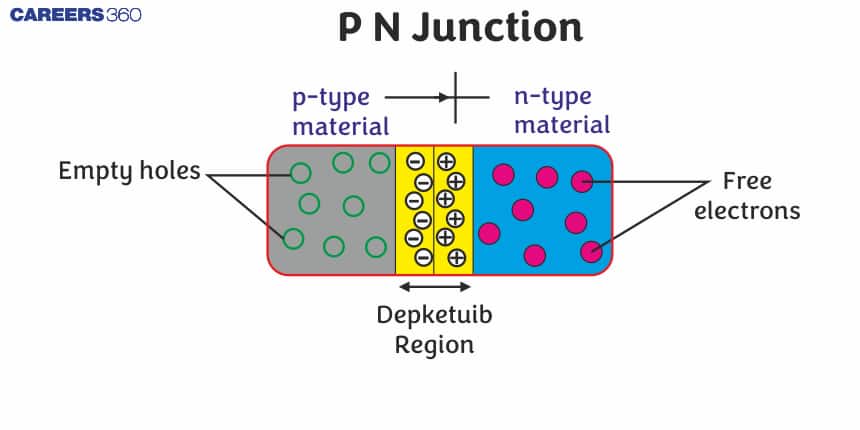
Definition of pn junction diode class 12: A pn junction is defined as a boundary between the two types of semiconductor materials which are p-type and n-type in a single crystal of semiconductor. P-type semiconductors are those semiconductors that are formed by the doping of trivalent elements and have holes as the majority charge carriers. N-type semiconductors are those semiconductors that are formed by the doping of pentavalent elements and have electrons as the majority charge carriers.
PN junction diode

Commonly Asked Questions

Q: What is a P-N junction?
A:
A P-N junction is the boundary or interface formed when a P-type semiconductor material is brought into contact with an N-type semiconductor material. This junction is the fundamental building block of many semiconductor devices, including diodes and transistors.
Q: How does a P-N junction diode differ from an ideal diode?
A:
Unlike an ideal diode, a real P-N junction diode:
Q: What is the significance of the knee voltage in a P-N junction diode?
A:
The knee voltage, also called the cut-in voltage or threshold voltage, is the forward voltage at which the diode starts to conduct significantly. It represents the point where the applied voltage overcomes the built-in potential barrier of the junction.
Q: What is the role of minority carriers in a P-N junction?
A:
Minority carriers (electrons in P-type and holes in N-type) play a crucial role in the reverse current of a P-N junction. They are responsible for the small reverse saturation current and contribute to the junction's temperature sensitivity and switching characteristics.
Q: What is a varactor diode, and how does it use the P-N junction properties?
A:
A varactor diode, also known as a varicap, is a P-N junction diode designed to exploit the voltage-dependent capacitance of the depletion region. By varying the reverse bias voltage, the capacitance can be changed, making varactors useful in voltage-controlled oscillators and tuning circuits.

Formation of PN Junction Diode

When n-type and p-type semiconductors are joined to form a pn diode junction, several processes occur.

We know that the concentration of electrons is high in n-type semiconductors as compared to p-type semiconductors and the concentration of holes is high in p-type semiconductors as compared to n-type semiconductors.

PN\ Junction Diode

When an electron diffuses from n to p, it leaves behind an ionized immobile positive ion which accumulates at the n-side of the junction. Similarly, when a hole diffuses from p to n, it leaves behind an ionized immobile negative ion which accumulates at the p-side of the junction. This charge region on both sides of the junction is called the depletion region.

Due to this positive charge region on the n-side and negative charge region on the p-side of the junction, an electric field directed from positive charge to negative charge develops due to this electric field electrons on the p-side move to the n-side and hole on the n-side moves to p-side. This motion of charge carriers due to the electric field is known as drift current.

PN Junction Drift

Also read -

Commonly Asked Questions

Q: How is a P-N junction formed?
A:
A P-N junction is formed by doping adjacent regions of a semiconductor crystal with different impurities. One region is doped with acceptor impurities to create a P-type material, while the other is doped with donor impurities to create an N-type material. When these two regions are brought into contact, a junction is formed at their interface.
Q: What happens at the P-N junction when it's first formed?
A:
When a P-N junction is first formed, electrons from the N-type region diffuse into the P-type region, and holes from the P-type region diffuse into the N-type region. This creates a depletion region at the junction, where there are no free charge carriers. An electric field is established across this region due to the charge imbalance.
Q: How does the doping concentration affect the properties of a P-N junction?
A:
Higher doping concentrations result in:
Q: What is the built-in potential of a P-N junction?
A:
The built-in potential, also called the contact potential, is the potential difference that naturally exists across a P-N junction at equilibrium (no external voltage applied). It results from the diffusion of charge carriers across the junction and typically ranges from 0.6 to 0.7 volts for silicon.
Q: What is the difference between drift and diffusion currents in a P-N junction?
A:
Drift current is caused by an electric field pushing charge carriers through the semiconductor. Diffusion current is caused by the movement of charge carriers from regions of high concentration to regions of low concentration. In a P-N junction, both types of currents contribute to the total current flow.

Working of PN junction diode

A pn junction diode is nothing but a pn junction provided with metallic contacts at both ends which are used to supply external voltage to the junction. It is a two-terminal device. The pn junction diode and its symbolic representation are shown below.
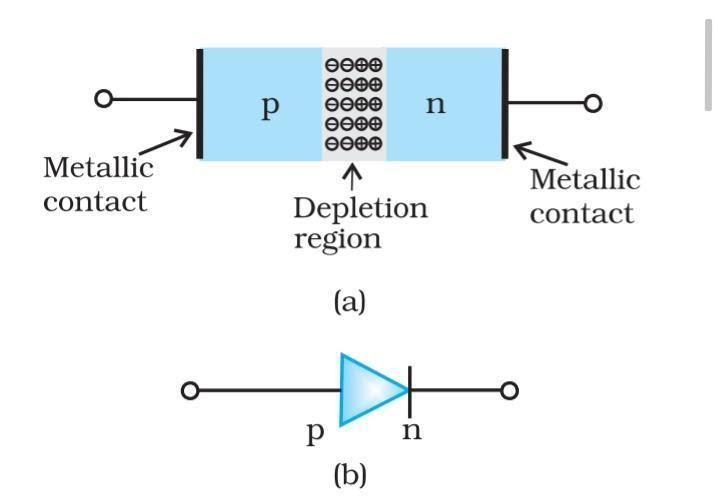
pn junction diode and its symbol

Biasing in PN junction diode

Biasing is a process of connecting the pn junction diode class 12 to the battery in order to provide the external input voltage. There are two different types of biasing methods depending upon which of the two terminals of the p-n junction are connected to which of the two sides of the battery.

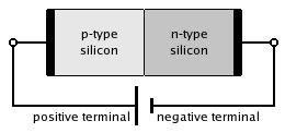
  1. Forward Bias: When an external voltage V is applied across the pn junction diode such that the p-side of the pn junction is connected to the positive terminal of the battery, the n-side of the pn junction is connected to the negative side of the battery, then the pn junction is forward biased.
NEET Highest Scoring Chapters & Topics
This ebook serves as a valuable study guide for NEET exams, specifically designed to assist students in light of recent changes and the removal of certain topics from the NEET exam.
Download E-book

PN Junction in Forward Bias

  1. Reverse bias pn junction: When an external voltage V is applied across a pn junction diode such that the p-side of the pn junction is connected to the negative terminal of the battery and the n-side of the pn junction is connected to the positive side of the battery, then the pn junction is reverse bias pn junction.
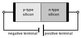
PN Junction in Reverse Bias

Related Topic,

VI characteristics of the diode of pn junction

The Vi characteristics of the diode of the pn junction are shown below. It represents the change in current with respect to a change in voltage or vice-versa. The x-axis represents voltage and the y-axis represents current. The VI characteristics of the pn junction can be explained according to three conditions.

Condition :

  • Zero bias: In this condition there is no external voltage is applied, hence the potential barrier is high and the circuit current is 0.
  • Forward bias: In the forward bias condition, the external voltage is applied which results in the reduced potential barrier and hence the current flows in the circuit.
  • Reverse bias pn junction: In the reverse bias pn junction condition, the external voltage is applied but this time potential barrier increases. A small amount of reverse saturation current flows but on increasing the applied voltage, the diode will break.
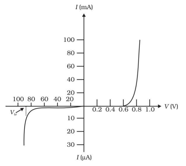
VI characteristics of pn junction

Commonly Asked Questions

Q: What is the depletion region in a P-N junction?
A:
The depletion region is an area at the P-N junction where free charge carriers (electrons and holes) have diffused across the junction and recombined, leaving behind fixed charged ions. This region is "depleted" of mobile charge carriers and acts as an insulator.
Q: How does the width of the depletion region change with applied voltage?
A:
When a forward bias is applied (positive voltage to P-type, negative to N-type), the depletion region narrows. When a reverse bias is applied (negative voltage to P-type, positive to N-type), the depletion region widens. This change in width affects the junction's electrical properties.
Q: What is forward bias in a P-N junction?
A:
Forward bias occurs when a positive voltage is applied to the P-type material and a negative voltage to the N-type material. This reduces the potential barrier at the junction, allowing current to flow more easily through the device.
Q: What is reverse bias in a P-N junction?
A:
Reverse bias occurs when a negative voltage is applied to the P-type material and a positive voltage to the N-type material. This increases the potential barrier at the junction, making it difficult for current to flow through the device.
Q: Why does a P-N junction conduct current easily in forward bias but not in reverse bias?
A:
In forward bias, the applied voltage reduces the potential barrier at the junction, allowing majority carriers to easily cross. In reverse bias, the potential barrier increases, making it difficult for majority carriers to cross. Only a small current due to minority carriers (reverse saturation current) flows in reverse bias.

Applications of PN junction diode

There are some of the common and important application of pn junction diode given below:

  • It has the potential to be used as a solar cell.

  • When the pn junction diode is reverse-biased, it can be used as a photodiode because it is sensitive to light.

  • In forward-biased conditions, the pn junction diode can also be used in LED lighting applications.

  • It is used in many electric circuits as a rectifier because it allows the current to flow only when the circuit is forward-biased.

Also, check-

Commonly Asked Questions

Q: How does a P-N junction behave as a rectifier?
A:
A P-N junction acts as a rectifier by allowing current to flow easily in one direction (forward bias) while blocking it in the other direction (reverse bias). This property is used to convert alternating current (AC) to direct current (DC) in power supplies and other electronic devices.
Q: How does temperature affect a P-N junction?
A:
Increasing temperature increases the number of electron-hole pairs generated thermally in the semiconductor. This leads to an increase in the reverse saturation current and a decrease in the forward voltage required for conduction. The overall effect is a reduction in the junction's resistance.
Q: What is breakdown voltage in a P-N junction?
A:
Breakdown voltage is the reverse bias voltage at which a P-N junction's resistance drops sharply, allowing a large current to flow. This occurs when the electric field in the depletion region becomes strong enough to break covalent bonds, creating a large number of electron-hole pairs.
Q: What are the two main types of breakdown in P-N junctions?
A:
The two main types of breakdown are:
Q: What is the capacitance of a P-N junction, and how does it change with bias?
A:
P-N junction capacitance, also called depletion capacitance, is the ability of the junction to store charge in the depletion region. It decreases with increasing reverse bias (as the depletion region widens) and increases with forward bias (as the depletion region narrows).

Frequently Asked Questions (FAQs)

Q: How does the P-N junction behave in the presence of ionizing radiation?
A:
Ionizing radiation can create electron-hole pairs in the semiconductor, leading to:
Q: What is the role of generation and recombination centers in P-N junctions?
A:
Generation and recombination centers are impurities or defects in the crystal structure that can:
Q: How does a P-N junction behave under extreme temperature conditions?
A:
At very low temperatures:
Q: What is the impact of junction depth on P-N junction characteristics?
A:
Junction depth affects several P-N junction properties:
Q: How does quantum tunneling affect P-N junctions in highly doped semiconductors?
A:
In highly doped semiconductors, the depletion region becomes very narrow. This allows charge carriers to tunnel directly through the potential barrier, even at low voltages. This quantum tunneling effect:
Q: What is the difference between homojunction and heterojunction P-N diodes?
A:
A homojunction P-N diode is made from a single semiconductor material (e.g., silicon) with different doping on each side. A heterojunction P-N diode is made from two different semiconductor materials (e.g., GaAs and AlGaAs). Heterojunctions can offer advantages such as:
Q: How does series resistance affect the behavior of a P-N junction diode?
A:
Series resistance in a P-N junction diode, caused by the bulk resistance of the semiconductor and contact resistances, leads to:
Q: What is the significance of the ideality factor in P-N junction diodes?
A:
The ideality factor, typically denoted as n, describes how closely a diode follows the ideal diode equation. It ranges from 1 (ideal) to 2, with most practical diodes falling between these values. A higher ideality factor indicates greater deviation from ideal behavior, often due to recombination in the depletion region or high-level injection effects.
Q: How does carrier lifetime affect the performance of a P-N junction?
A:
Carrier lifetime is the average time a minority carrier exists before recombining. Longer carrier lifetimes result in:
Q: How does a P-N junction behave under reverse recovery conditions?
A:
Reverse recovery occurs when a diode transitions from forward to reverse bias. During this time: